VITA
TECHNICAL BULLETIN
GRAIN MILL FOR HOME USE
by
Walter B. Booher
The grinder detailed here is made almost entirely of 1"
lumber and
can be constructed easily by someone used to working with
wood. It
will grind corn, wheat and other grains to coarse or fine
texture.
The designer of this grain mill, Walter B. Booher, has been
a VITA
Volunteer for 11 years.
For some time Booher, who has been a machine
shop tool designer and high school teacher, owned and
operated a
small factory. Now
retired, Booher remains an active technical participant
in VITA programs.
Please send testing results, comments, suggestions and
requests for
further information to:
Technical Bulletins
VITA Publications Service
1600 Wilson Boulevard, Suite 500
Arlington, Virginia 22209, USA
ISBN 0-86619-098-8
VOLUNTEERS
IN TECHNICAL ASSISTANCE
1600 WILSON BOULEVARD, SUITE 500
ARLINGTON, VIRGINIA 22209, USA
HAND-POWERED GRAIN MILL
TOOLS AND MATERIALS
Tools -
Materials -
Hammer
12 feet of 1" x 6" seasoned
sheathing
Hand cross cut saw
lumber
Auger brace and 1/4, 1/2 and 7/8
2 feet 1" x 10" sheathing lumber
inch auger
bits 2 feet 2" x
8" framing lumber
Round file
3 feet 2" x 4" framing lumber
Coping saw or key hole saw
1 piece 1/2" x 14" cold rolled steel
Breast drill and 1/8" twist drill
12 - 1 1/2" x 8" flat head wood
One flat file
screws
One-three corner file
3 - 1/2" steel washers
1/2" x 13" die and die handle
4 - 1" x 4" carriage bolts
5/61" die
1 - 1/2" wing nut
Wood chisel
1 - 3/8" x 5" carriage bolt
Half round wood file
2 - 1" thick flat stones large
Tin shears
enough to scribe a 4 1/2"
Screw driver
disc
<Fig. 1>
05p01a.gif (437x437)

DETAILS
Through the
following discussion 1" lumber refers to the standard
board thickness for surfaced sheathing lumber in the United
States. It
actually measures only about three
quarters of an inch in thickness.
All dimensions are in inches.
Lumber
used should be flat and well
seasoned. The
numbers in the next
section refer to part numbers shown
in Figure 2 and subsequent detailed
05p01b.gif (600x600)
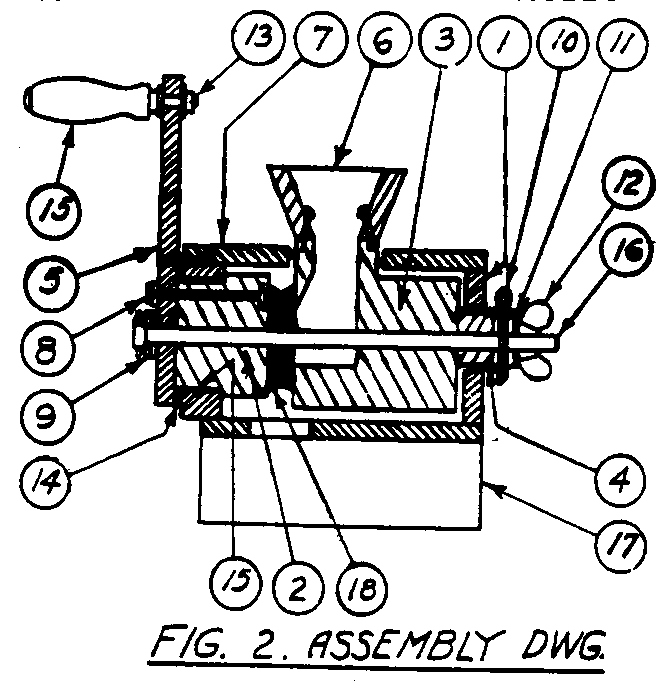
part sketches.
1. Grinder Body -
make of 1" x 6"
05p02a.gif (600x600)
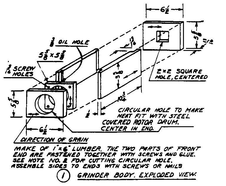
pine or hard wood lumber.
Circular
hole can be cut with coping saw or
jig saw but for a better and quicker
way to cut see Notes 1 and 2, Figures 3 and 4.
05p05a0.gif (600x600)
2. Rotor - See Note
2. Take care to
05p02b.gif (600x600)
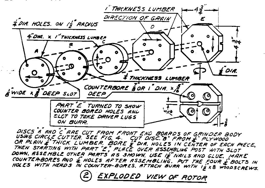
bore the 1/2" holes thru each part
where required accurately and at right
angles to the surface of the part.
If
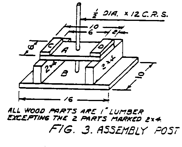
when placed on the assembly
post, it does not lay flat to
the assembly post surface
marked "A" in Figure 3 or against
05p05a.gif (600x600)
an adjacent part because
the hole is not bored
straight, remove it from the
assembly post and use a round
file in the hole carefully until
it will lay flat.
Use a
few spots of glue between parts.
Be careful in nailing so nails
will not interfere with boring
the 1/4" holes later.
Keep
the nails within 1" of the center
post. 1 1/2"
finishing
nails are about right.
It is a help in
getting the
metal band snugly on the rotor
drum to form the 3/8" lip on one
end first, then bend the band around some round object that
is about
3" in diameter.
Next put it on the rotor drum with the one lip engaged
in the slot. Use
strong twine or flexible wire to pull band snugly
around drum and mark position of the second lip.
Remove from rotor,
form the second lip and cut off excess.
The band may need to be formed
a little with the fingers.
It should now fit snugly.
3. Stationary Burr
Holder - In boring 1/2" holes and assembling follow
05p03a.gif (600x600)
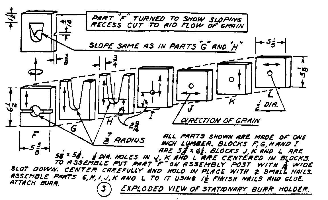
the instructions given under (2).
Assemble he parts using a few spots
of glue and nails. 1
1/2" finishing nails are about right.
4. Follow
instructions under (2) Rotor for assembling parts of the
thrust block.
05p03b.gif (600x600)

5. The 1/4"
holes can best be located by placing the rotor and crank all
05p03c.gif (600x600)
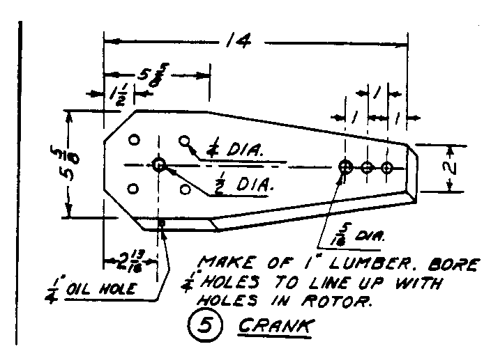
on the assembly post.
With bolts in lace thru rotor mark location
for holes on crank
by tapping with
a hammer. Oil
hole in the
crank is bored
to reach the
1/2" hole. This
will supply oil
to the steel
shaft.
6. Attach hopper to
top of stationary burr holder with screws.
See
05p03d.gif (600x600)
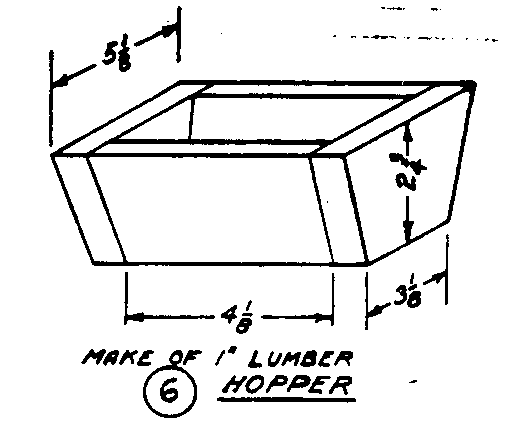
Figure 2.
05p01b.gif (600x600)

7. Cover
05p03e.gif (600x600)

8. Four 1/4" x
4 1/2" carriage bolts wit
nuts and 8 washers.
9. Two steel washers
for 1/2" diameter
bolts.
10. Two 1/8"
diameter x 2" cotter key.
If a larger diameter cotter key is used,
drill the hole to suit.
The hole should
not in any case be more than 5/32".
11. Three steel
washers for 1/2" bolt.
12. One 1/2"
winged nut.
13. One 5/16"
diameter carriage bolt
threaded 1 1/2".
File square shank
under head to roundness.
Length 4 1/2".
14. Clearance Block
- The purpose of
05p04a.gif (437x437)
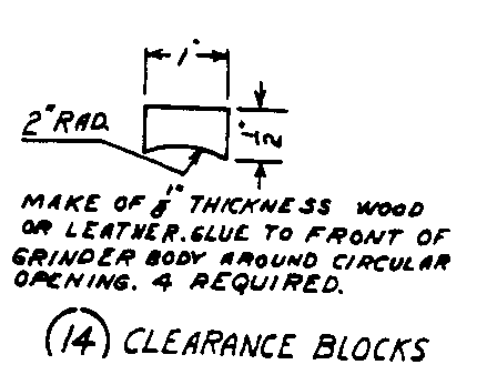
the clearance block is to keep the
crank from rubbing the
front of the grinder.
Locate the clearance
blocks at even quarters
around circular
opening in front of
grinder body.
15. Rotor Drum Band
05p04b.gif (486x486)
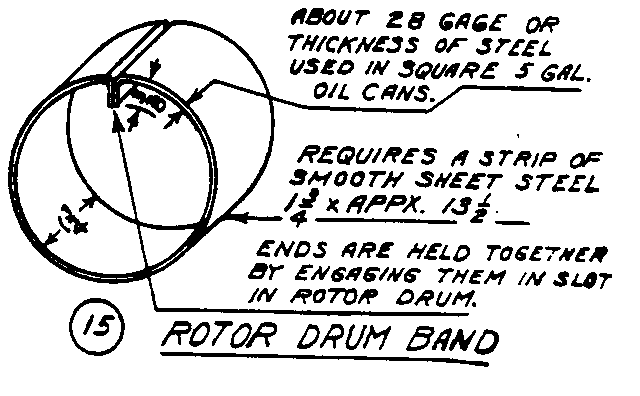
In making this part
and attaching it to
rotor read the discussion
under Rotor
(2).
16. Steel Shaft -
Threading
05p04c.gif (600x600)
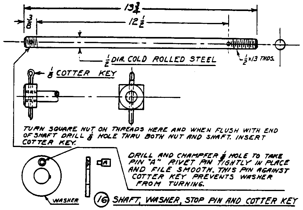
is U.S.
standard, 1/2" x 13
threads per inch.
17. Grinder Stand.
05p04d.gif (600x600)

18. Two cast iron
burrs. See
materials.
FINAL ASSEMBLING
After all parts are
completed
the next step is to fully assemble
the mill. The rotor
with burr attached
is placed in its position in
the circular opening.
Attach the
crank. Next put the
stationary burr
holder in position and insert the
steel shaft thru both parts.
Put
the thrust block In place, insert the cotter key, put on
steel washer
and run up the winged nut.
In making the final adjustment it may be
necessary to add one or more steel washers between thrust
block and
burr holder or to shorten the thrust block.
When the winged nut is
tight, there should be a little play between the cotter key
and the
bottom of the slot in thrust block.
Before putting on
the cover turn the rotor and observe the burrs
carefully. They
should remain flat to each other when rotor is
turned. If there is
an opening which travels around as the rotor
turns, a shim is needed under the burr on the rotor.
Mark the place
and note thickness of shim required.
If the opening remains stationary
a shim is needed under the burr on the burr holder.
Remove he
necessary part and add a shim.
Of course, both burrs may need shims.
A little glue under the shim makes a permanent job.
NOTES -
The purpose of the
following is to facilitate and speed up the job
of making the mills.
It is assumed the mills will be made in a carpenter
shop as a business.
The notes along with Figures 3 and 4 describe
05p05a0.gif (600x600)

two devices that will be found very useful in shops making
these
mills.
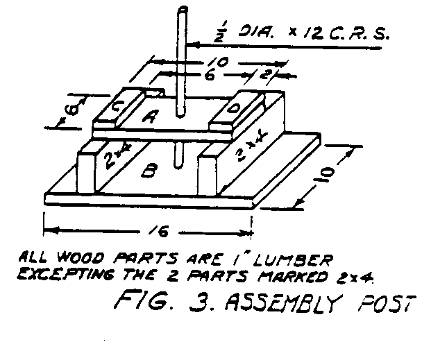
NOTE 1 - See Figure
3. The use of
05p05a.gif (600x600)

the assembly post is described under
(2) and (3). In
constructing the
assembly post, care should be taken
to make it very solid and strong and
the steel post must be square with
the surface marked "A" in Figure 3.
A good way is to build the entire
wood part of the device "C" and "D"
before boring the holes for the steel
post. When ready to
bore these holes,
bore thru "A" first, then push the bar
thru to "B" and testing carefully with
a square move top of bar until it tests
square both ways then strike the bar
on its top end to mark position of the
auger hole in "B".
Last, put on "C"
and "D".
NOTE 2 - See Figure
4. The
05p05b.gif (600x600)

purpose of this device is to cut
the circular discs out of the end
boards of the grinder body.
Test
each on the assembly post to be
sure the holes are square thru
these members. Use a
round file
if the member does not lay flat
on "A" of the assembly post.
Place the pieces one at a time on
the rod of the disc cutter.
Remove
the steel rod from the assembly
post and pass the steel rod of the
disc cutter thru both holes of the
assembly device. The
assembly device with disc cutter in place should
now be held in a bench vise or fastened to a wall so the
shaft is horizontal
and at a convenient height for turning.
Turn the crank and
exert a gentle pressure to bring the cutter into play.
The steel cutter
should be of tool steel. A six inch
length of
drill rod is excellent.
If this is not available, a screw driver
with approximately a 1/4" diameter shank can be shaped
up with a
file to do the job.
In operating the disc cutter cut only half way
thru the member then reverse and complete from other side.
For greater
strength the cutter can be made more then 1/16" in
thickness. This will
make the discs that compose the rotor drum
fit too loosely even after the steel band is on but the
difficulty
is easily corrected by giving the drum several turns of
heavy wrapping
paper before the steel band is applied.
The paper should be
glued to the drum.
The stone
buhrs. Make them from suitable stone
that can be found along
lake shores, river banks and in open fields.
Sandstone and shale are too
soft; some granite is too hard to work.
As a test, you should be able to
drill a hole readily with a masonery bit.
Many kinds of stone, including
most limestone, are suitable for buhrs.
It will pay to spend considerable
time hunting for just the right two stones that will not
require too much
labor to complete.
The stones should be betewen 3/4" and 1 1/8" thickness,
have one flat side and be large enough to scribe a 4
1/2" diameter circle
on them. Of course,
you probably won't find stones with perfectly flat
sides, and it will help to work a side flat by rubbing it
hard over well
hardened cement walks or slabs.
Some hard sand sprinkled on the slab will
make the cutting easier.
It is safer not to use a hammer and cold chisel
on the stone until it is firmly mounted on its buhr holder.
<Step 1>
05p07.gif (486x486)

After smoothing and
mounting the buhrs,
use chisel to form
a 3/16" deep
basin which is
2 3/4" diameter.
Make 2 identical
buhrs. The outer
edge does not
have to be perfectly
round but
edges should be
trimmed sufficiently
so they are balanced
when running.
When mounting the stones on the buhr holders, be sure to
have the
flat surface of each buhr in a parallel plane with the flat
surface
of its buhr holder.
If the surface being mounted against the
buhr holder is irregular, hollow out sane areas of the
mounting
block to conform with the irregular areas of the stone.
Use epoxy
to cement the stones to their mounting blocks.
Use epoxy freely.
After it has set overnight, fill in any visible openings
around the edges of the
stone and mounting block.
It is well to have the center hole drilled in each
but all chisel work should be done after mounting.
In working stone by hand
some variations are inevitable but if you hold a close
approximation to the
plan shown in detail #16 your stone should grind high grade
flour.
<Step 2>
05p08y.gif (600x600)

========================================
========================================

