51033-BK
VITA
TECHNICAL BULLETIN
HOME FLOUR MILL
by
WALTER B. BOOHER
This grain mill,
except for the buhrs (which are stone), shaft, bolts,
screws, and glue, is built of wood. Plywood is specified,
but plain boards
can be used. In
1976, at Miami, Florida, prices, the material for the mill
cost US $6-8.
The mill can be powered with a 1/4 Horse Power electric
motor, wind power,
or by hand. Although
the machine shown here is intended for single family
use, the designer feels the machine could be enlarged easily
by increasing
all dimensions. To make a mill having a 9" diameter
metal buhr (rather than
the 4 1/2" diameter one shown here) the mill body might
double in size;
however, the drive shaft need be enlarged only from
3/4" to 1".
The designer of this grain mill, Walter B. Booher, has been
a VITA Volunteer
for 11 years. For
some time Booher, who has been a machine shop tool designer
and high school teacher, owned and operated a small
factory. Now
retired, Bocher remains an active technical participant in
VITA programs.
Please send testing results, comments, suggestions and
requests for further
information to:
VITA
1600 Wilson
Boulevard, Suite 500
Arlington,
Virginia 22209 USA
Tel:
703/276-1800 * Fax: 703/243-1865
Internet:
pr-info@vita.org
ISBN
0-86619-112-7
VOLUNTEERS IN
TECHNICAL ASSISTANCE
Some Notes Before Beginning
The buhrs shown are two flat stones.
However, the machine has been built and
used with buhrs made of fired clay and then sandblasted to
roughen them.
Initial results were good.
Stone buhrs must be sharpened about once a year.
Before beginning, please read the entire plan
carefully. Pay particular attention
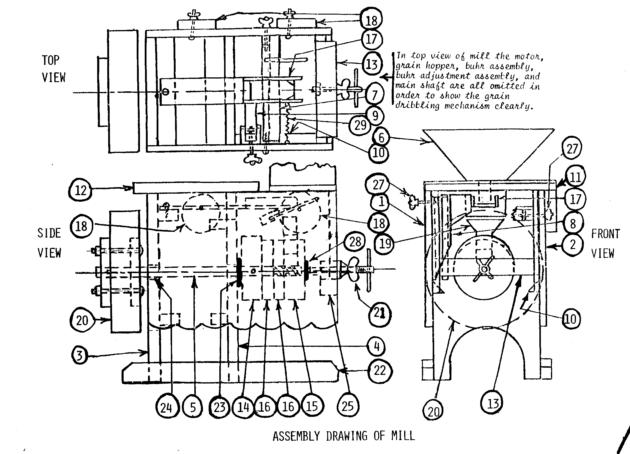
to the arrangement of parts as shown in the assembly drawings.
Each part will be discussed in some detail.
The numbers below correspond
directly to the parts being discussed; in other words number
1 is a discussion
of part 1.
GOOD LUCK!
THE
MILL BODY
Parts (1) (2) (3) (4):
hfm0010.gif (600x600)

Use 1/2" thickness good quality plywood for parts (1)
and (2) and 3/4" thickness
hfm0020.gif (600x600)

plywood for parts (3) and (4).
All parts must be exactly square and dimensions
hfm001.gif (600x600)

accurate. Use epoxy
glue in the four main joints. The use
of 2" long finishing
nails will avoid the necessity for using clamps.
Be sure the mill body is
perfectly square before setting it aside for the glue to
harden overnight.
(1) Subassembly, Left Side.
(2) Subassembly, Right Side.
hfm002.gif (600x600)
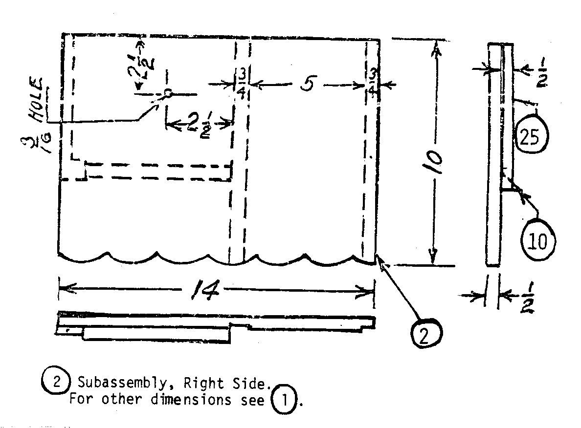
For other
dimensions see (1).
(3) End Section.
hfm03.gif (600x600)

(4) Center Bulkhead.
Overall
hfm04.gif (540x540)

dimensions same as
detail (3),
note other
variations.
(5) Drive Shaft. Use
3/4 dia. cold rolled steel for this part.
Use a 1/4 or
hfm005.gif (600x600)

3/8 inch thickness
grinding wheel or a 3/8 dia. round file to cut the spiral
groove on one end. Cut the spiral groove about 5/32 of an
inch deep. Follow
drawing as closely as possible; however, some unevenness in
the screw will not
prevent it from doing the job.
(6) Grain Hopper. Use plywood throughout.
hfm006.gif (600x600)

(7) Dribbler Trough Height Adjustment Bar. Use 3/4"
thickness pine.
hfm007.gif (437x600)

Stove bolt is
3/16" by 2". The winged nut
is turned hard against the
head of the bolt with epoxy against the head and in the
threads. This
makes a solid unit of the bolt and winged nut.
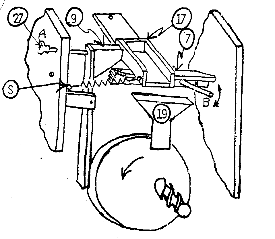
(8) Rocker cradle.
This part including the
hfm08.gif (540x600)

rocker bar, dribbler trough height
adjustment
bar and the revolving buhr holder are
all shown digramatically in the sketch below.
Notice that the eccentric action of the buhr
holder provides the shaking action that
causes the grain to work slowly to the end
of the dribbler trough where it falls into
the funnel shaped part #19 that directs it
hfm019.gif (540x540)

into the buhrs.
(9) Rocker Bar.
hfm09.gif (540x540)

(10) Shield the deflect meal.
This
hfm009.gif (353x393)
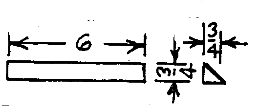
part helps to
deflect the meal
into the s orage drawer.
Two are
required.
(S) This little spring holds the
hfm010.gif (600x600)
dribbler trough
against the
Rocker Bar. It is
attached at one
end to the dribbler as shown and the
other end is attached to the inside
wall of the mill.
The end attached
to the mill wall should be about
1/2" lower than the end attached to
the dribbler.
(11) The grain hopper base is attached to the left side of
the mill body by
hfm011.gif (600x600)

the use of two
butt hinges. The hinges should have
about a 1" long pin
and 1" long leaf.
The purpose of this manner of attaching the grain hopper
is to make it possible to adjust the clearance between the
grain hopper
spout and the dribbler trough. See parts 11 and 17.
hfm0110.gif (600x600)

(12) Motor base is also attached to the
hfm012.gif (353x353)

left side of mill
body by two hinges
or same size.
(13) Buhr Adjustment Bar.
Hardswood
hfm013.gif (486x486)

is preferred for
this
part.
(14) Rotating Buhr Holder.
hfm014.gif (600x600)

Use two pieces each 3/4" thickness
plywood by 5" x 5".
Before cutting
the pieces round cut the 5/16" by 5/16"
slot in one of the pieces as shown.
Fasten the two pieces together using
about four screws and glue.
The 3/4 diameter
hole should next be located.
This
hole should pass exactly thru the center
of the 5/16 x 5/16" slot.
Before boring
this hole, however, use a compass to
scribe the 4 1/2" diameter circle.
Then
move the center of the compass 3/16" as
shown and scribe a circle of 4 7/8" diameter.
Now bore the 3/4" diameter hole.
Saw out the circle on the outer line.
Complete the part by using a round file
to make the hole about 1/8" larger in
diameter at both ends but let it remain
3/4" diameter at its center.
The
eccentric action of this buhr holder
provides the action that shakes the
dribbler trough.
(15) Stationary Buhr Holder.
hfm0150.gif (486x486)
Use one piece of 1" thickness plywood and one
piece of 1/2" thickness.
First, saw out the
two 4 1/2" diameter pieces.
Then lay out on
the 1" thickness piece, the 1" wide section
that is to be cut out to receive part #19.
Cut out for this piece with the grain of the
wood. See assembly drawing.
Next bore 3/4"
hfm003.gif (600x600)
diameter hole in 1/2" thickness piece and
attach the small steel plate.
(See detail
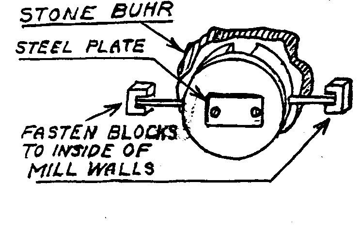
#28.) Note also the sketch below showing
the two 1/4" dowel pins, one in either side of
this buhr.
holder.
Shown also
are two
parts not
shown in
drawings. These
two dowels and the
blocks into which they slide hold the
stationary buhr in place and prevent it from
turning. By loosening the buhr adjustment screw
(part #21) and removing part #13, the entire
hfm021.gif (230x600)

hfm013.gif (437x486)

stationary buhr is removed.
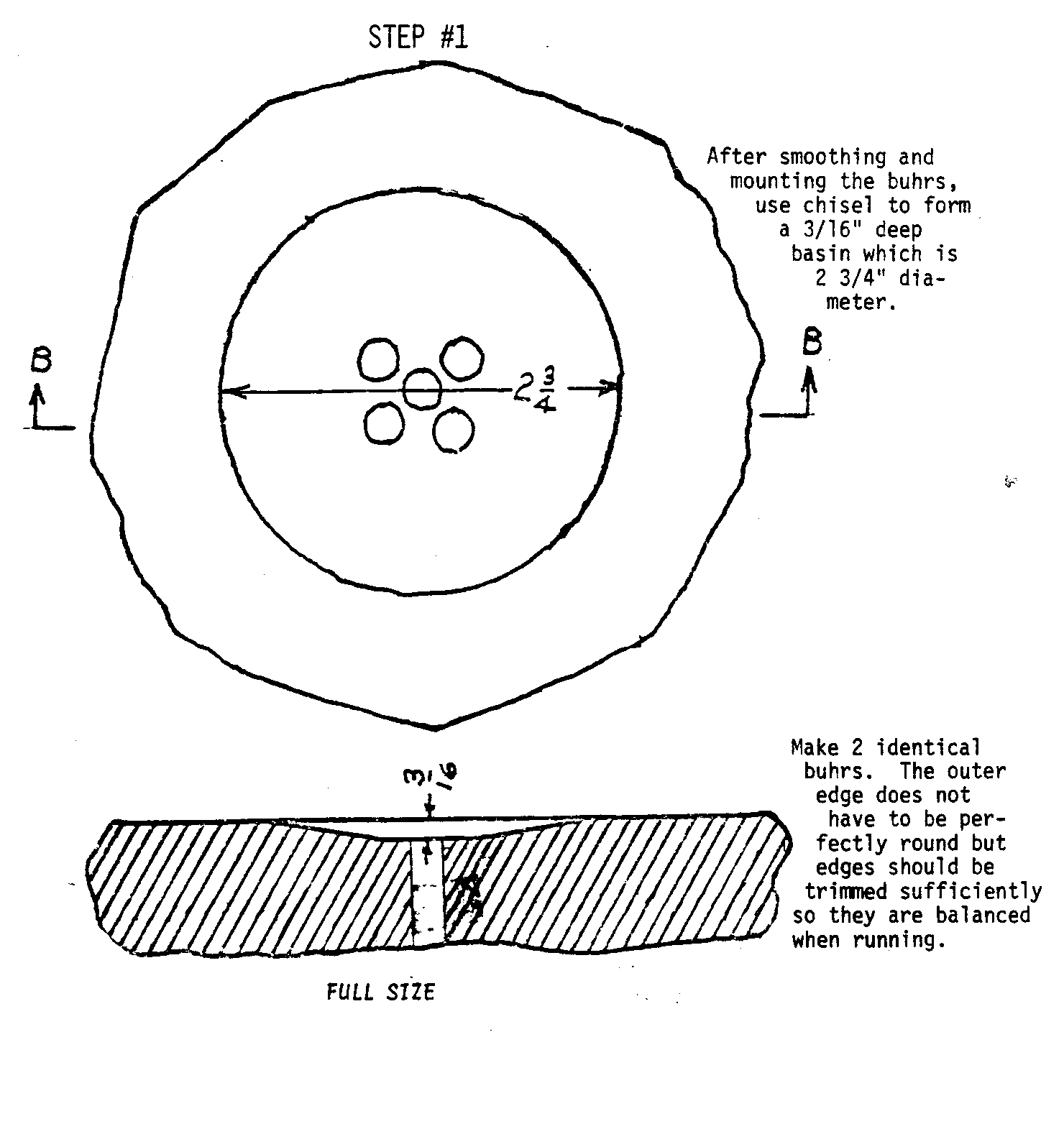
(16) The stone buhrs.
Make them from suitable stone that can be found along
hfm0160.gif (600x600)
lake shores,
river banks and in open fields.
Sandstone and shale are too
soft; some granite is too hard to work.
As a test, you should be able to
drill a hole readily with a masonery bit.
Many kinds of stone, including
most limestone, are suitable for buhrs.
It will pay to spend considerable
time hunting for just the right two stones that will not
require too much
labor to complete.
The stones should be betewen 3/4" and 1 1/8" thickness,
have one flat side and be large enough to scribe a 4
1/2" diameter circle
on them. Of course,
you probably won't find stones with perfectly flat
sides, and it will help to work a side flat by rubbing it
hard over well
hardened cement walks or slabs.
Some hard sand sprinkled on the slab will
make the cutting easier.
It is safer not to use a hammer and cold chisel
on the stone until it is firmly mounted on its buhr holder.
When mounting the stones on the buhr holders, be sure to
have the
flat surface of each buhr in a parallel plane with the flat
surface
of its buhr holder.
If the surface being mounted against the
buhr holder is irregular, hollow out some areas of the
mounting
block to conform with the irregular areas of the stone.
Use epoxy
to cement the stones to their mounting blocks.
Use epoxy freely.
After it has set overnight, fill in any visible openings
around the edges of the
stone and mounting block.
It is well to have the center hole drilled in each
but all chisel work should be done after mounting.
In working stone by hand
some variations are inevitable but if you hold a close
approximation to the
plan shown in detail #16 your stone should grind high grade
flour.
(17) Grain Dribbler should be just
hfm11.gif (437x437)

long enough to
dribble grain
into part 19. In assembling the
hfm019.gif (486x486)

mill reduce the 10" dimension to
suit.
(18) Eccentrics - Make 2.
These two parts
hfm018.gif (256x437)

should be
identical. Use epoxy under and
around the head of the 3/16" bolt (inside mill
body) on which these eccentrics turn.
The one
eccentric serves as a belt tightener and the
other raises or lowers the grain hopper.
Use
winged nuts for convenience.
(19) Use light gauge tinned sheet metal to make this
hfm019.gif (486x486)

part.
The auxiliary sketch shown here will
help you. Use tin
shears to make 1/4"
cuts in each of the four corners of
the square tube.
Solder the seam
of this tube then solder the seam
of the rectangular funnel shaped
section. Then, with
two of the
upper edges of the tube bent to
conform with the funnel-shaped
section, place the two parts
together and solder.
(20) The balance wheel is made of cement (concrete).
Use one part portland
hfm0200.gif (353x540)

cement to two
parts sand. You can make the form for
it by sawing out a
circle from 3/4" thickness plywood.
The diameter of the circle should be
9" and the hole in center 3/4" diameter.
Have a second 3/4" thickness
block so the hole will have a depth of 1 1/2".
When the 3/4" diameter
shaft is placed in the form, this hole must hold the shaft
exactly vertical
with the 9" diameter circle (see sketch).
Saw out the two 5" diameter circles
and bore for bolts.
(If you plan to turn the mill with a crank, make
these circles 7" diameter.
These bolts are 3 1/2" long.
Or make these bolts 5" long if you plan to attach a
windwheel to this balance wheel.)
The form for the
wheel is made of light gauge sheet steel.
(Cardboard
can also be used.)
Make 3" wide by 30" long.
Bend around the 9" disc and tack or nail.
Assemble and pour the concrete.
Let concrete harden
for about four days.
The sketch shows the form set
up ready for the concrete.
A section of the form is
shown cut away for clarity of the drawing.
The form
including the shaft should be well coated with heavy
grease so cement will not stick to form.
Use a
straight edge to strike off the cement after pouring.
Avoid disturbing bolts.
Note 5/16" x 5/16" slot
thru the upper disc to take the 1/4" pin thru shaft
when assembled. Wait
until concrete has hardened four
days before putting the upper disc in place.
(21) Buhr Adjustment Screw.
Use in conjunction with a square nut and a winged nut.
hfm021.gif (167x600)

(22) Make 2 pieces 3/4 x 1 1/2 x 1 1/2" as shown in
assembly drawing (page 1).
hfm003.gif (600x600)

Use 3/4"
thickness pine lumber. Make the foot 1
1/2" high and 15 1/2" long.
Bore 1/4" to suit matching holes in details #1 and #2.
(23) Use two steel washers with one copper washer between.
(24) Bronze Bearing.
This can be a standard bronze sleeve bearing acquired at
a bearing supply
store, or it can be simply a short length of copper water
pipe. If the light
gauge pipe is used, it will be advisable to use a hacksaw
to cut the piece lengthwise and remove about 1/8".
Then compress it to fit
the shaft more snugly.
Before installing, roughen the outer surface to hold
the epoxy better.
The bearings should be put in place only after the body of
the mill is permanently assembled and epoxy is hard.
Put the bearings in
place using epoxy.
Then slip the shaft thru before epoxy hardens.
With this
precaution, the bearings will be held in alignment.
Still another way to provide the bearing is to make a
bearing entirely of
epoxy. Bore a
1" diameter hole for the shaft, make a collar to hold the shaft
exactly in the center of the hole in parts (3) and (4) then
with the shaft
hfm001.gif (600x600)

well greased and in place work epoxy all around the shaft
until it fills the
space between the 3/4" diameter shaft and the 1"
diameter hole. Remove the
shaft and bore the oiling hole after epoxy has hardened and
you will have very
satisfactory bearings.
(25) See Part (2).
hfm025.gif (317x393)

hfm002.gif (540x540)

(26) Meal Bin.
hfm026.gif (186x437)

(27) This part is a 3/16" x 2" round headed stove
bolt having a winged nut
turned on it clear to the head.
In turning the winged nut on, just before
it reaches the head work epoxy well into the threads so it
will be tight on
the threads.
(28) See main assembly drawing on mill.
hfm028.gif (285x353)
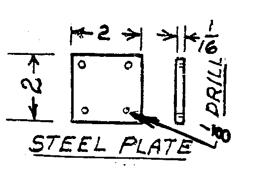
Also see detail
(15).
hfm0150.gif (437x437)

VITA Technical Bulletins offer do-it-yourself
technology information on a
wide variety of subjects.
The Bulletins are idea generators
intended not so much to provide a definitive
answer as to guide the user's
thinking and planning.
Premises are
sound and testing results are provided,
if available.
Evaluations and comments based on each
user's experience are requested.
Results
are incorporated into subsequent editions,
thus providing additional guidelines
for adaptation and use in a
greater variety of conditions.
========================================
========================================

