 |
| |||||||||||||||||||||||||||||||||||
Institut f�r berufliche Entwicklung e.V.
Berlin
Original title:
Arbeitsmaterial f�r den
Lernenden
“Arbeiten an Oberfr�smaschinen”
Author: G�nter Hanisch
First edition © IBE
Institut f�r berufliche Entwicklung e.V.
Parkstra�e
23
13187 Berlin
Order No.: 93-35-3405/2
|
| |||||||||||||||||||||||||||||||||||
1. The Purpose of Routing Machine Milling
The routing machine is a wood-working appliance. A great many processing operations are possible because of the special arrangement of the work spindle and the nature of the tools. The keynote fields of application are:
- profile milling and surface milling of workpiece narrow and wide faces,
- milling curved profiles and contours,
- copy milling operations
- producing ornaments and decorations.
|
| ||||||||||||||||||||||||||||||
Operations with Routing Machines - Course: Mechanical woodworking techniques. Trainees' handbook of lessons (Institut f�r Berufliche Entwicklung, 13 p.)
2. Assembly of a Routing Machine
The operations undertaken by the machine precondition the following main functions of a routing machine:
- stable workpiece support and all-round workpiece freedom of movement at table level,
- axial application and interruption of the milling tools,
- a high tool rotational speed,
- sound tool chucking facilities and quiet spindle running,
- simple and safe operations of machine elements, easily reached operating elements.
The heavy cast iron stand ensures a quiet and vibration-free running of the machine and the arrangement of the various elements enable application as:
- routing machine
- bore miller and
- shaping machine

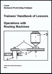
Figure 1 - Routing machine
1 setting device for the locator pin, 2 machine table, 3 locator pin, 4 chuck, 5 guard basket, 6 milling support, 7 gear cover, 8 differential spacer, 9 compensating screw, 10 motor, 11 machine frame, 12 hand wheel to arrest the compensating mass, 13 foot level, 14 hand wheel for table adjustment
2.1. Operation Mechanism of the Machine
In order to undertake surface milling, milling out and bores the spindle, in addition to the rotational movement, must also execute an axial feed movement.
Spindle lowering ensues by depressing the foot lever. The equalization mass compensates as counterweight for the weight of the milling support. Thereby the actuating forces are reduced. The spindle can be lowered for bore operations by depressing the foot lever or raised for routing operations, depending on the position of the reversing lever on the crank lever.

Figure 2 - Spindle
limitation
1 spiral spacer, 2 stop, 3 compensating screw
The spindle stroke can be limited for setting the milling depth. The greatest possible spindle stroke is 100 mm. A stroke limitation of around 40 mm can be set by turning the spiral spacer. The stop can also be adjusted heightwise and, co-ordinated with the spiral space, make possible a height adjustment of between 0 and 100 mm. The stop screw makes possible fine setting. Instead of a spiral spacer other machine types feature a revolver head with a maximum of eight setting screws. Thereby it is possible to store a number of setting dimensions for later work assignments.
The machine table features a height adjustment facility. Setting ensues by turning the hand wheel. The shaft guide of the machine table can be arrested by means of a set-screw.
A locator pin has been positioned in a cavity beneath the spindle axis. The locator pin can be used for various tool diameters, that is to say it is interchangeable, for it features a height adjustment facility by means of which the pin can be raised in several stages over the table surface. The locator pin acts as stop for various locating facilities.
2.2. Drive
The routing machine is driven by an electric motor with a wattage of some 1.5 kW and a rotational speed of approx. 2850 min-1. The spindle rotational speed can be switched as desired by means of a flat belt gear or, using interchangeable belt pulley pairs, to 3000 min-1,12000 min-1 or 18000 min-1.
The lower spindle rotational speed is used for drilling simple bores into the borehole walls. It is desirable to use the medium rotational ranges when operating as shaping machine.
When undertaking routing operation with a small tool diameter, select the greatest rotational speed for attaining the necessary cutting speed.
Switching over to another rotational speed ensues by exchanging the one belt pulley pair for another set with a different speed ratio. The various belt pulleys are available as machine accessories.

Figure 3 - Machine drive
1 flat belt pulley pair, 2 V-belt pulley pair, 3 motor, 4 milling spindle
Excessively high spindle rotational speeds exert a considerable strain on the spindle bearings. These elements must be properly maintained and tended to in line with the machine instruction manual provisions. All the movable parts of the machine must be kept thoroughly clean and greased regularly after a certain number of operating hours.
Depending on the hardness of the material, milling speeds of 20 ms-1 to 80 ms-1 are required. Cutting speeds of 1 ms-1 to 15 ms-1 are required for bores.
The cutting speed “v” in ms-1 can be calculated from the formula v = d · p · n
Example:
Which cutting speed “v” applies when, given a spindle rotational speed of n = 12000 min-1, a tool measuring 20 mm in diameter (d) is to be used? (p = 3.14)
Solution:


v = 12.56
ms-1
The cutting speed is 12.56 ms-1.
The calculated cutting speed is still too low for routing operations. The determined cutting speed is, however, sufficient for boring and milling operations. As regards boring, the cutting speed is the top limit and the tool yields clean bore walls. The release of chips creates difficulties with deep boreholes. This rotational speed should therefore only be employed for bore operations of minimal bore depth.
Exercise:
Which maximum cutting speed results when using a 16 mm chamfer mill at a spindle rotational speed of 12000 min-1?
|
known: | |
unknown: |
|
d = 16 mm |
v = d · p· n |
v =? |
|
n = 12000 min-1 | | |
|
p = 3.14 | |
|
2.3. Chuck and Tool Mounting
The utilization of single-cutter tools presupposes the eccentric chucking of the tools in the clamp. Consequently, a clearance angle is formed between tool surface and working face whereby lateral milling vis-�-vis the tool axis becomes possible. The eccentric tool clamping causes unbalance during rotation. This in turn, would lead to vibrations in the machine and subsequently, machine damage and serious accidents.

Figure 4 - Single-edged
milling tool in chuck
1 balancing screw, 2 chuck, 3 tool, 4 knife cutting circle, 5 eccentricity
Therefore, every tool clamp must be balanced jointly with the tool. For this reason tapped holes are inserted into eccentric chucks. During balancing screws are turned into these bores for the eccentrically chucked tool. The chuck is tightened in a balancing roll for balancing. The roll is then made to roll slightly on an even and thoroughly even glass plate. By altering the distribution of screws in the chuck the weight distribution is changed around until the roll remains stationary in any position. Then the chuck is sufficiently balanced.
Ensure that the chuck cone is free from grease and dust and in sound condition when the chuck is positioned in the spindle.
Figure 5 - Chuck
mounting to the milling spindle
1 milling spindle, 2 cone, 3 differential nut, 4 knife cutting circle, 5 eccentricity
The positioned chuck is tightly clamped with a differential nut which is only moderately tightened. The chuck has been correctly placed if merely two thread leads are visible below the differential nut.
The knife cutting circle can be altered on the eccentric chuck by varying the plan angle between tool cutter and the line chuck to tool axis. The mill width of the tool can thus be aligned simply to the processing job in hand.

Figure 6 - Eccentric chucking
of the routing tools (example (1), (2), (3))
1 clearance angle, 2 knife cutting circle
|
Plan angle c= 0º |
cutting possible but tool inclined to bum as no plan angle available. |
|
Plan angle c= 30º to 50º |
optimal cutting conditions and best quality, knife cutting circle becomes smaller. |
|
Plan angle c = 90º |
cutting is no longer possible as the workpiece rear face extends beyond the knife cutting circle. The cutter is not brought into play. |
Staggered chuck sizes are required for chucking the various tool types. These chucks feature differing eccentricities. Consequently, however, a small number of tool suffice for setting up differing working widths.
Table 1: Setting table to determine the chuck sizes for cylindrical routing machines
| | |
d2 at = | | |
d2 at = | ||
|
d1 |
F |
50º |
30º |
d2 |
F |
50º |
30º |
|
2.5 |
0.5 |
2.85 |
3 |
10.5 |
3 |
12.6 |
13.2 |
|
2.5 |
1 |
3.2 |
3.4 |
11 |
3 |
13.2 |
13.8 |
|
3 |
1 |
3.7 |
3.9 |
11 |
4 |
14 |
14.7 |
|
3.5 |
1 |
4.2 |
4.4 |
12 |
4 |
15 |
15.6 |
|
4 |
1.5 |
5.1 |
5.3 |
13 |
4 |
15.9 |
16.9 |
|
4.5 |
1.5 |
5.6 |
5.9 |
13 |
5 |
16.8 |
17.8 |
|
5 |
1.5 |
6.1 |
6.4 |
14 |
5 |
17.6 |
18.6 |
|
5.5. |
2 |
6.9 |
7.35 |
15 |
5 |
18.6 |
19.4 |
|
6 |
2 |
7.4 |
7.75 |
16 |
5 |
19.4 |
20.4 |
|
6.5 |
2 |
8 |
8.4 |
16 |
6 |
20.4 |
21.4 |
|
6.5 |
2.5 |
8.5 |
8.85 |
17 |
6 |
21.4 |
22.4 |
|
7 |
2.5 |
8.8 |
9.4 |
18 |
6 |
22.4 |
23.2 |
|
7.5 |
2.5 |
9.4 |
9.9 |
19 |
6 |
23.2 |
24.4 |
|
8 |
2.5 |
9.9 |
10.4 |
19 |
7 |
24 |
25.2 |
|
8 |
3 |
10.2 |
10.7 |
20 |
7 |
25.2 |
26.4 |
|
8.5 |
3 |
10.6 |
11.2 |
20 |
8 |
26 |
27.4 |
|
9 |
3 |
11.2 |
11.6 |
22 |
8 |
27.5 |
29 |
|
9.5 |
3 |
11.6 |
12.2 |
22 |
9 |
28.5 |
30 |
|
10 |
3 |
12.2 |
12.6 |
|
|
|
|
c = routing machine plan angle, d1 = tool diameter, d2 = knife cutting circle, F = chuck size
Example:
A milling width of d2 = 20 mm is required.
Which chuck size should be selected?
Which workpiece diameter is used?
According to Table 1, when using a tool with a diameter d1 = 16 mm in the chuck size F = 5, the result is a possible milling width of d2 = 19.4 to 20.4 mm
Table 1 does not feature the various milling widths
d2. How can the not cited value d2 = 6.0 mm be
calculated?
_________________________________________________________________________
_________________________________________________________________________
_________________________________________________________________________
Centrical chucks are also used for multi-cutter tools. Balancing is not necessary with these chucks. The knife cutting circle remains constant and is not subject to change through setting measures.
|
| |||||||||||||||||||||||||||||||||||
3. Routing machine tools
The selected tool always depends on the nature of the processing operation. Single- and double-edged tools are used for milling operations with a routing machine.
Single-edged tools permit a variety of setting values and can be simply resharpened. Such tools must be clamped into an eccentric chuck, otherwise chip removal is not possible.
Double-edged tools can be clamped into an eccentric chuck. Only one tool cutter operates and, as in the case of single-edged tools, the knife cutting circle can be variously set. When using a centrical chuck both tool cutters operate and the knife cutting circle remains constant.

Figure 7
(1) Single-edged tool
(2) Double-edged tool
Tools with a taper shank or tap shaft can only be centrically chucked.

Figure 8
(1) Tool with tap shank
(2) Tool with cylinder shank
(3) Tool with taper shank
Why does only one cutter operate during chip removal given the
eccentric cucking of a double-edged
tool?
_________________________________________________________________________
_________________________________________________________________________
_________________________________________________________________________
Table 2: Types of routing tools
|
Designation Presentation |
Special features |
|
cylindrical routing machine
|
single-edged tool for eccentric chucking for milling grooves, curves, recesses and bores |
|
fold cutter with tap shank
|
double-edged tool with screw thread for centrical chucking only for fold milling - not for bore operations! |
|
Dovetailing machine
|
single-edged tool for eccentric chucking for yielding dovetailed comer joints |
|
bun cutter
|
single-edged tool for eccentric chucking for yielding burr joints, milling burr grooves and the burr spring |
|
half round cutter
|
single - and double - edged tool executions possible double-edged only for centrical chucking for milling half round profiles and narrow faces |
|
quarter round cutter
|
single-edged for eccentric chucking at a radius of up to 8 mm from 10 mm double-edged for centrical chucking |
|
chamfer cutter
|
double-edged for centrical chucking to yield chamfer grooves, half and quarter chamfers |
|
grain cutter
|
single-edged tool for eccentric chucking |
|
fold cutter with taper shank
|
with taper shank for centrical chucking tool is clamped into the spindle without chuck and tightened by means of the differential nut |


|
| |||||||||||||||||||||||||||||||||||
4. Tool Guiding Possibilities
Stop strips or a stop rule can be attached to the machine table surface for tool guidance.
The table surface features tap bores to retain the holding screws for the stops. In addition, the stops can be held by means of screw clamps.
Curved models can be prepared at the locator pin. Commensurately, the locator pin can be raised at various heights above the table surface.
The tool shall not touch the locator pin. Tool and locator pin can otherwise be damaged and there is a considerable accident risk. The model only has a very small bearing surface at the locator pin and should, therefore be of particularly hard and durable material.
Special guide facilities must be prepared for milling operations with varying milling directions within the range of broad surfaces and for milling contours. Thereby, the sequence of the milled profile is determined by the sequence of the locator slot in the lower face of the guidance facility. During this process the locator pin is in the locator groove and serves as stop. The top side of the guide facility features stops and holding possibilities for the workpiece being processed.
In the Instruction Example 05.3. “Quarter Chamfer and Half Chamfer” the handling of a copying facility as guide device is described.
The following should be heeded when setting up this facility:
- the device must be easy and safe to handle
- during processing the workpiece shall not change its position in the device
- the locator pin must slide easily into the locator groove
Stops and guide strips are screwed, glued or nailed to the base plate.
Figure 9 - Cross-section of a
copying device
1 workpiece, 2 workpiece chucking facility, 3 base plate, 4 guide strip, 5 locator pin
|
| |||||||||||||||||||||||||||||||||||
5. Basic Provisions of Labour Safety when Operating Routing Machines
The routing machine is a wood working machine giving rise to the lowest number of accidents. The required labour safety provisions can be easily ensured. The requirements in point are the following:
- order and tidiness around the machine are essential preconditions for accident-free operations- the tool spindle must glide automatically into the top rest position during boring operations. This process ensues through the compensating mass
- the tool spindle must be capable of arrest at the highest position during milling operations. This requirement is met with the help of a retainer pin at the spindle guide. By means of removal and turning through 90º the pin no longer operates. This is necessary when switching to drilling operations
- the tool must evidence its highest setting within the protective device, the guard basket
- the guard basket must prevent the hands from touching the workpiece
- only use sharp tools. Blunt tools can cause accidents
- copying devices must include chucking elements for workpiece clamping. Handle grips are required
- persons with long hair must do on a head covering
- finger rings must be removed prior to commencing work operations

Figure 10 - Guard basket for
operations on the routing
machine