 |
| ||||||||||||||||||||||||||||
|
| ||||||||||||||||||||||||||||
Institut f�r berufliche Entwicklung e.V.
Berlin
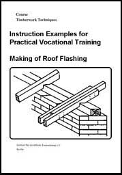
Original title:
Lehrbeispiele f�r die berufspraktische Ausbildung
"Herstellen
von Dach�berst�nden"
Author: Rolf Becher
First Edition © IBE
Institut f�r berufliche Entwicklung e.V.
Parkstra�e
21-23
13187 Berlin
Order No.: 93-33-3603/2
|
| ||||||||||||||||||||||||||||
Preliminary Remarks
The present booklet contains 4 selected instruction examples which are exclusively related to eaves flashings. Making of eaves flashings requires work on site and in the workshop as well.
The Instruction Examples 3.1. and 3.2. have been selected so that practising of the examples can be done separately or successively, one based on the other one.
Instruction Example 3.3. includes the calculations necessary for making the templates required for an eaves flashing to be made on a roof structure to be built.
Example 3.4. explains the sequence of operations in template making for re-proofing of buildings.
The necessary materials, machines, hand tools, measuring and testing means and auxiliary accessories are specified for each example to facilitate the preparation and execution of the work. Moreover, the previous knowledge, which is necessary in addition to knowledge of the technique Making of Roof Flashings, is also stated for each example and should be recapitulated at the beginning.
The order of working steps given in the sequence of operations is to be followed, in order to achieve good quality of work.
A working drawing showing the required shapes and dimensions is also attached to each example.
The working drawings 3.1. and 3.2. are required for the first two examples.
|
| ||||||||||||||||||||||||||||
Instruction Example 3.1.: Working of Boards for a Roof Base Facing
The face and bottom boards for a couple roof base facing are to be worked.
Material
Boards with tongue and groove planed on one side, board lengths between 3000 mm and 4100 mm

Figure
Hand tools and machines
Smoothing plane, circular saw bench
Measuring and testing means
Folding rule, measuring tape (if necessary)
Auxiliary accessories
Pencil, work bench (working table)
Necessary previous knowledge
Reading of drawings, measuring and testing, planing, operation of the circular sawing machine, fundamental arithmetic operations
|
Sequence of operations |
Comments |
|
1. Determine the board length. |
Use attic framing drawing! |
|
- 20 bays would be 4 board lengths |
Roof base facing must cover the total length of the
building. |
|
- Initial board |
Use attic framing drawing! |
|
- Intermediate board 5 · 803 mm
= 4015 mm |
over 5 bays, |
|
- |
over 2 bays, since 3 + 15 + 2 = 20 bays |
|
2. Determine the board width. |
Consider maximum board width. |
|
3. Determine the number of boards. |
Use laid-out eaves flashing and determination of step 1 above. |
|
- Bottom boards: 130 mm wide |
Roof base facing is to be provided at both sides of the couple roof. |
|
- List of boards: | |
|
4. Select boards of adequate length and width in timber yard. |
Consider surface quality, too! |
|
5. Store boards according to width at the side of the circular saw bench. |
Make sure that there is enough freedom to move! |
|
6. Saw boards to width. |
Use laid-out eaves flashing. |
|
7. Chamfer boards |
Put board flat on work bench. |
|
8. Store boards for transportation. |
Protect stored boards against possible damage during storage! |

Attic
Framing
|
| ||||||||||||||||||||||||||||
Instruction Example 3.2.: Making of a Roof Base Facing
The wooden beam heads projecting by 300 mm are to be covered by a roof base facing.
Material
Prepared face and bottom boards
Figure
Hand tools
Hammer, frame saw, wrecking bar with claw, nail punch
Measuring and testing means
Folding rule, bevel protractor
Auxiliary accessories
Pencil, measuring rod 4015 mm long, cleat, nails 3.1/80, 2.8/70
Necessary previous knowledge
Reading of drawings, measuring and testing, sawing, scribing, nailing, nail punching.
|
Sequence of operations |
Comments |
|
1. Check the scaffolding. |
Working direction from left to right. |
|
2. Store boards on scaffolding. |
Ensure freedom of movement! |
|
3. Cut square initial board (1) at right end. |
Use try square. |
|
4. Place and fasten provisionally board (1). |
Place right end of board centrically at 4th beam head. |
|
5. Scribe initial board. |
Align over gable wall and scribe-mark. |
|
6. Take off initial board and scribe angular line. |
Use a try square. |
|
7. Saw initial board to length. |
Saw square! |
|
8. Place measuring rod at initial board (1) and transfer size. |
Do it exactly! |
|
9. Nail initial board (1). |
Locate points of nails in the board in nail holes in the beam
head and drive in the nails. |
|
10. Scribe and saw to length initial boards (2), (3) and (4). |
Measuring rod to be placed flush. |
|
11. Nail initial board (2). |
Insert tongue in groove of board (1) and press it in with lever
pressure. |
|
12. Nail initial boards (3) and (4). |
Insert tongue in groove of boards and place boards. |
|
13. Place measuring rod of 4015 mm length over the next beam heads and check the size. |
Place it from centre to centre of beam heads. |
|
14. Scribe and saw to length all four boards for the other joints of the roof base facing according to the checked size. |
Use a try square. |
|
15. Nail roof base facing boards. |
Nail the boards joint by joint proceeding similarly as with the first joint (initital boards). |
|
16. Saw square at left end and fasten provisionally final board (1). |
Use a try square. |
|
17. Scribe length of board. |
Align over gable wall and scribe size. |
|
18. Take off, scribe and saw to length final board (1). |
Use a try square. |
|
19. Place measuring road at final board and transfer length. |
Place flush at one end. |
|
20. Scribe and saw to length final boards (2), (3) and (4) according to size taken. |
Place measuring rod exactly. |
|
21. Nail final boards. |
09 Consider type of nails! |
|
22. Close roof base facing at both ends. |
Use the cuttings. |
|
23. Nail the roof base facing. |
Nail in the centre of the beam bays |
|
24. Clean the work place. |
Pick up wooden cuttings and clean scaffolding. |
Eaves
Flashing
|
| ||||||||||||||||||||||||||||
Instruction Example 3.3.: Template Making for a Rafter Foot
The template for the rafter foot of a purlin roof to be built shall be made and the real rafter length be determined.
Dimensions
Width of building: 8000 mm
Height of roof: 3000 mm
Cross
section of rafter: 80/140 mm2
z (horizontal distance of eaves
flashing) = 500 mm
n (height of inferior purlin above surface of attic beam)
= 80 mm
o (square attachment timber) = 100 mm

Figure
Hand tools
Frame saw
Measuring and testing means
Folding rule, carpenter's steel square
Auxiliary accessories
Paper, pencil, hand sketch, abrasive paper, board approx. 1600 mm long and 140 mm wide
Necessary previous knowledge
Reading of drawings, measuring and testing, scribing, sawing, smoothing
|
Sequence of operations |
Comments |
|
1. Determine real rafter length. |
Formula: Spl = SplR + y |
|
| |
|
| |
|
h = 3000 mm |
|
|
z = 500 mm | |
|
SplR = (42 + 32) m2 | |
|
SplR = 5000 mm | |
|
| |
|
y = 625 mm | |
|
Spl = 5000 mm + 625 mm | |
|
Spl = 5625 mm |
|
|
2. Determine x0 |
x0 is the size from the inferior purlin line up to
the rafter foot, not the length for the template! |
|
b = 4000 mm |
|
|
| |
|
n = 80 mm | |
|
h = 3000 mm |
|
|
o = 100 mm | |
|
| |
|
y1 = 125 mm | |
|
| |
|
z1 = 273.3 mm | |
|
| |
|
x0 = 966.6 mm | |
|
3. Put straight board of approx. 1600 mm length on work bench. |
Board width to comply exactly with rafter height. |
|
4. Scribe angular line at left end and mark with section mark. |
Use steel square. |
|
5. Measure in and mark the size x0 from the angular line. |
Scribe only thin and short line. |
|
6. Measure in and scribe square attachment timber. |
Do not scribe over the entire length but only scribe thin line in the area of the rafter foot line. |
|
7. Mark the size y1 on the long leg of the square. |
Scribe thin line. |
|
8. Place square with marked size y1 at x0 mark and swivel the square until point of intersection with square attachment timber is reached. |
Place it exactly! |
|
9. Scribe surface of inferior purlin and front face of inferior purlin. |
Scribe a thicker line at the short leg of the square and a thin line at the long leg. |
|
10. Scribe front face of inferior purlin. |
Place long leg of square at thin line and scribe bird's mouth depth. |
|
11. Scribe template length. |
Measure from x0 line. Use a square. |
|
12. Saw out template. |
Saw exactly and perfectly square. |
|
13. Smooth cut surfaces with abrasive paper. |
Use fine-grained abrasive paper! |
|
14. Transfer scribed lines of bird's mouth to upper narrow side of template. |
Scribe thin line. |


Template for a Rafter
Foot
|
| ||||||||||||||||||||||||||||
Instruction Example 3.4.: Re-proofing of Buildings
The cover straps shall be produced for re-proofing a building by displacement of the rafter foot of a purlin roof.

Figure
Dimensions
Cross section of roof rafter: 80/140 mm2
Thickness
of cover straps: 40 mm
Horizontal distance of eaves flashing: 500 mm
Hand tools and machines
Frame saw, hand plane, bevel protractor, band saw
Measuring and testing means
Folding rule, carpenter's steel square, water level
Auxiliary accessories
Straightedge 2000 mm long, pencil, abrasive paper, board of 140 mm width and 2000 mm length
Necessary previous knowledge
Reading of drawings, measuring and testing, plumbing (perpendicularity), scribing, sawing, curving, planing, smoothing
(1) scribed straightedge
(2) board for template
(3) curve
of rafter foot
|
Sequence of operations |
Comments |
|
Steps 1 to 6 are to be carried out at the building! |
|
|
1. Check the scaffolding. |
Stability, bracing, covering of uprights, guard rail. |
|
2. Insert the straightedge between the roof boards and the inferior purlin and press it against the roof rafter. |
Insert it approx. 1000 mm. Make sure that it contacts the roof boards and the roof rafter. |
|
3. Transfer the front face of the outside wall onto the straightedge by scribing the perpendicular line. |
Use a water level. |
|
4. Transfer front face of inferior purlin onto straightedge. |
Mark only! |
|
5. Remove straightedge and insert it at several roof rafters to check the scribed lines. | |
|
6. Count the roof rafters. |
Is necessary for the number of cover straps required. |
|
All other steps are to be carried out in the workshop | |
|
7. Take perpendicular line from straightedge by means of bevel protractor. |
Working direction from left to right! |
|
8. Put board for template (approx. 2 m long) on work bench and scribe on it square attachment timber. |
Scribe a thin line. |
|
9. Scribe angular line at right end of board and mark the section to be cut off. |
Go only as far as necessary to produce a rectangular cut. |
|
10. Measure in and mark 500 mm from angular line to the left. |
Measure on 8. |
|
11. Scribe perpendicular line through marking. |
Use bevel protractor. Perpendicular line is front face of inferior purlin. |
|
12. Scribe surface of inferior purlin. |
Place square leg at perpendicular line so as to have point of intersection with 8.! |
|
13. Take from straightedge, measure in on template and mark the size up to front face of outside wall. |
Measure on 8.! |
|
14. Scribe perpendicular line through marking and mark with "FW". |
"FW" means front face of outside wall. |
|
15. Mark horizontal distance of eaves flashing (500 mm) at long leg of square. |
Apply only thin marking. |
|
16. Place tongue of bevel protractor at perpendicular line, displace short leg of square at tongue so as to have point of intersection at upper edge of template board! |
Place square and bevel protractor tongue exactly. |
|
17. Scribe template length and mark the section to be cut off. |
Use a square. |
|
18. Profiling. |
Scribe the curve so that it can be easily sawn out with the band saw! |
|
19. Saw out the template. |
Saw it out at exact angles. |
|
20. Smooth the template with abrasive paper. |
Use fine-grained abrasive paper. |
|
21. Measure length of cover straps and select timber for cover straps in the timber yard. |
Number of cover straps has been counted on site. |
|
22. Transport the timber to the work bench and store it. |
Ensure freedom of movement. |
|
23. Put template successively on the timber for the cover straps to be produced and scribe cover straps. |
Scribe cover straps on one side only. |
|
24. Saw out the cover straps. |
Saw the curve exactly on the band saw! |
|
25. Plane the visible sides of the cover strap foot. |
Use a hand plane. |
|
26. Smooth curve with abrasive paper. |
Use coarse-grained abrasive paper. |
|
27. Store cover straps for transportation. |
Store cover straps so that they cannot be damaged or get dirty. |
Re-proofing of
Buildings