 |
| ||||||||||||||||||||||||||||||||||||||||||||||||||||||||||||||||||||||||||||||||||||||||||
Department of Roads
His Majesty's Government of
Nepal
© John Howell 1999-06-03
ISBN 1 86192 170 5
This document is an output of the Nepal-UK Road Maintenance Project, which was undertaken jointly by His Majesty's Government of Nepal and the Department for International Development of the United Kingdom. The views expressed are not necessarily those of either government.
Please copy all or any part of the Site Handbook or Reference Manual for your own use. If you plan to reproduce any of the material in these documents please be sure to acknowledge its source and author.
Editor: Omar Sattaur
Design: Chris Jones, Design for Science
Photography: Jane Clark, John Howell, Shankar Rai and Ishwar
Sunwar
Graphics: Mark Fletcher, Smith Ward Design
Typesetting: Paul Samat
Print: Ernest G Bond Ltd

Figure
|
|
Published by |
Funded by |
Department for |
| |
Department of Roads |
94 Victoria Street, London, SW1E 5JL, UK | |

|
| ||||||||||||||||||||||||||||||||||||||||||||||||||||||||||||||||||||||||||||||||||||||||||
Acknowledgements
This manual of Roadside Bio-engineering has been developed from an enormous amount of experience, gained throughout the road network of Nepal between 1984 and 1998. It is written for the exceptional conditions found in Nepal (characterised mainly by very active geomorphology, steep slopes, intense rainfall and a restricted economy) and the techniques have been tested under those conditions.
So many people have been involved that it is quite impossible to acknowledge them all. Nothing could have been achieved without the full support of the Department of Roads, the financial support of the Department for International Development of the United Kingdom and the administrative support of Roughton International. In writing this manual I have drawn on material and comments from a large number of people. The main personal contributions and support are listed below.
Department of Roads: Varun Prasad Shrestha, Niranjan Prasad Chalise, Mohan Bahadur Karki, Bharati Sharma, Suresh Kumar Regmi, Shyam Prasad Adhikari, Medini Prasad Rijal, Madan Gopal Maleku, Basu Dev Jha, Keshav Pokhrel, Ananda Kumar Batajoo, Indu Sharma Dhakal, Biplabh Karki, Jamuna Bahadur Shrestha, Vishnu Prasad Shrestha, Yogendra Kumar Rai, Deepak Raj Maskey, Ajay Kumar Mull, Bijay Chapagain, Shankar Prasad Rajbhandari, Buddhi Prasad Neupane, Sudarsan Lal Shrestha, Deepak KC, Raj Kumar Maharjan.
Department for International Development, United Kingdom: Jane Clark, Peter Roberts, Martin Sergeant, Ed Farrand, Janet Seeley.
Eastern Region Road Maintenance: Ishwar Sunwar, Indra Kafle, Shankar Rai.
Mountain Risk Engineering Unit, Tribhuvan University: Megh Raj Dhital, Narendra Man Shakya, Samjwal Ratna Bajracharya, Siddhi Bir Karmacharya, Padma Bahadur Khadka.
Others: Cliff Lawrance (Transport Research Laboratory), Bob George (Wolverhampton University), Hare Ram Shrestha and Govinda Mallick (Sustainable Infrastructure Development Foundation), Mohan Dhoj Joshi and Kalyan Thapa (Third Road Improvement Project), Werner Paul Meyer (Helvetas), Simon Howarth (Sir Mott MacDonald and Partners), Stephen Eagle (Forestry and Bio-engineering Consultant), Dev Bir Basnyet (Alliance Nepal), John Millband (WSP International), the staff of Roughton International and Scott Wilson Kirkpatrick, Keshar Man Sthapit (Ministry of Forests and Soil Conservation), Ramesh Bikram Karky (Karky Law Chambers), Pushpa Lal Moktan (New Era), Peter Branney (Forestry and Rural Development Consultant), Paul Balogun (Natural Resources Economics Consultant), Keshar Man Bajracharya (Royal Nepal Academy of Science and Technology), and Narendra Paudyal (Botanical Illustrator).
The manual production team in the United Kingdom was Omar Sattaur (Editor) and Chris Jones (Designer).
John Howell (Living Resources Limited).
June
1999.
|
| ||||||||||||||||||||||||||||||||||||||||||||||||||||||||||||||||||||||||||||||||||||||||||
Introduction

Figure
The nature and scope of bio-engineering
USING THE SITE HANDBOOK
This handbook provides the information needed to design, plan, implement and maintain roadside bio-engineering works. It also covers the establishment and maintenance of bio-engineering nurseries. It is intended that the handbook cover all subjects that an engineer would need on site. (The companion Reference Manual provides background and supporting information and is intended for office use.)
Each subject is covered in a separate section and sections are marked with a vertical coloured bar for easier reference.
Words that appear in the glossary have been highlighted in orange.
THE NATURE AND SCOPE OF ROADSIDE BIO-ENGINEERING
What is this handbook for?
This Site Handbook is to inform engineers and overseers on the use of bio-engineering in Nepal. It is written specifically for use on roadside slopes. It covers all of the practical aspects of designing, planning, implementing and maintaining bio-engineering site works. The companion Reference Manual provides all the supporting information required.
What is bio-engineering?
Bio-engineering is the use of living plants for engineering purposes. Vegetation is carefully selected for the functions it can serve in stabilising roadside slopes and for its suitability to the site. It is usually used in combination with civil engineering structures. Bio-engineering offers the engineer a new set of tools, but does not normally replace the use of civil engineering structures. Incorporating the use of bio-engineering measures usually offers a more effective solution to the problem. The materials and skills are all available in rural areas, however remote.

Placing jute netting on a steep
cut slope
What does bio-engineering do?
· Bio-engineering can be used to protect almost all slopes against erosion1.
· Bio-engineering reduces the instances of shallow planar sliding2.
· Bio-engineering can be used to improve surface drainage and reduce slumping3.
1 Erosion is the gradual wearing away of soil (or other material) and its loss, particle by particle.2 Planar sliding is a mass slope failure on a slip plane parallel to the surface (i.e. not rotational). It is the most common type of landslide and is usually shallow (less than 1.5 metres deep). It is also called a debris slide or a translational landslide.
3 Slumping is a form of saturated flow of soil or debris. It occurs mostly in weak, poorly drained materials, when a point of liquefaction is reached following heavy rain. It is usually shallow (less than 500 mm deep).
Bio-engineering systems work in the same way as civil engineering systems and have the same functions. They are effective at depths of up to 500 mm below the surface. They are not effective for deep-seated landslides or failures.
Designs that incorporate bio-engineering are usually the most effective and the most economic solutions for the shallow-seated problems listed above. Although bio-engineering costs more in the short term than the 'do nothing' approach, in the long term there should be additional benefits from reduced maintenance costs.
How does bio-engineering work?
Bio-engineering structures can provide a range of engineering functions (see below). The civil engineering systems given in the table for comparison are the nearest equivalent, but are not always appropriate for slope stabilisation in Nepal.
Where should bio-engineering be used?
Bio-engineering techniques for stabilising slopes should be used on:
· all areas of bare soil on embankment and cut-face slopes;· wherever there is a risk of gullying;
· all slopes where there is a risk of shallow slumps or planar slips of less than 500 mm depth;
· any slope segment in which civil engineering structures are planned or have been built, and the surface remains bare;
· any area that has failed and needs to be restored, other than rock slopes;
· any area, such as tipping and quarry sites, or camp compounds, that requires rehabilitation.
As with all engineering works, it is most important that the techniques selected are correct for the site to be treated, and that the work is carried out with all due care and attention.
How is bio-engineering done?
In the Department of Roads, executive authority and responsibility for bio-engineering lies with the Division Chief or Project Manager, with assistance from the Regional Office or from the Geo-Environmental Unit. A Supervisor is usually responsible for each nursery (as the naike), and others for specialised bio-engineering labour gangs. Engineers and Overseers are now expected to understand bio-engineering enough to organise programmes under their chief's direction.
Some bio-engineering contractors operate nationally, but most are local, 'D class' contractors.
When is bio-engineering done?
Bio-engineering works are planned in the same way as other works, following the annual pattern of planning, budget estimation and submission, detailed site assessment, estimation and implementation. However, some differences exist: the need to establish and maintain nurseries, for example, and the fact that timing is controlled by seasons.
The main engineering functions of structures, with examples of civil and bio-engineering structures
|
FUNCTION* |
CIVIL ENGINEERING TECHNIQUE |
BIO-ENGINEERING TECHNIQUE |
COMBINATION OF BOTH |
|
Catch |
Catch walls |
Contour grass lines |
Catch wall with bamboos above |
|
Armour |
Revetments |
Grass carpet |
Vegetated stone pitching |
|
Reinforce |
Reinforced earth |
Densely rooting grasses |
Jute netting with planted grass |
|
Anchor |
Soil anchors |
Deeply rooting trees |
Combination of anchors and trees |
|
Support |
Retaining walls |
Large trees and large bamboos |
Retaining wall with bamboos above |
|
Drain |
Surface or sub-surface drains |
Downslope vegetation lines |
French drains and angled grass lines |
* The six main engineering functions are defined in Section 1.2 on page 15 and are elaborated in the Reference Manual.
|
| ||||||||||||||||||||||||||||||||||||||||||||||||||||||||||||||||||||||||||||||||||||||||||
Safety Code of Practice for Working on Slopes
|
1. This code is designed to promote the safety of all Department and Contract personnel while working on slopes at sites where persons are at risk of falling a distance of more than 2 metres. 2. No-one may gain access to the site unless they are authorised by the Engineer or the Contractor. 3. No person may work unaccompanied unless they are on a very gentle slope (less than 30º slope). All personnel must leave the slope to take refreshments, meals etc. 4. During site works, all fragile slopes shall be clearly marked off and personnel informed of the dangers. 5. Extreme care must be exercised on slopes during adverse weather conditions as wind, rain, fog and darkness create their own hazards in addition to the hazards inherent in slope work. The site in-charge must assess the conditions with great care access to the slope. Only in emergencies may persons go on to slopes in heavy rain or during the hours of darkness. In such cases, no person shall go on to the slope unaccompanied. 6. All access equipment, ropes and tackle must be regularly inspected and adequately maintained in a sound condition. 7. Where persons could fall over the edge of a slope, temporary guard rails or ropes are to be installed where practicable. All persons exposed to a risk of falling must be provided with a secure and well-anchored safety line. Such a rope Must be of sufficient strength to provide them with safe arrest in the event of a fall. 8. Care must be taken to prevent tools and loose objects falling from the slope. Loose articles should be raised or lowered in a safe manner. They should not be carried up or down ladders, unless in the case of small items, which may be carried In a suitable shoulder bag. 9. Any scaffolding that is used must be composed of good quality materials. Bamboos should be freshly cut, of strong and flexible nature. Scaffolding must be of appropriate capacity and correctly erected by competent persons. 10. Ladders must be in good condition and adequate for the job. Ladders should extend one metre beyond the landing point and must be on a firm base, correctly pitched and lashed as soon as is possible. Unlashed ladders must be 'footed'. 11. If there is any potential hazard to personnel below where the slope work is taking place, adequate temporary warning notices, barriers and a 'look out' person shall be employed. Where appropriate, standard traffic warning and control measures must be taken. 12. Appropriate protective clothing shall be issued, including, where necessary, protective helmets and boots with steel toe caps and slip-resistant soles. |

How safe are the working practices
in your area?
Site safety
The engineer or contractor is always responsible for the safety of people working on a site. Where a contractor is engaged, then the responsibility is usually delegated to him. Although accidents are often blamed on workers, the fault lies with management alone in more than 60 per cent of cases. The executive authority must ensure that safe practices are followed.
Roads are intrinsically dangerous. They are made even more dangerous by the presence of maintenance gangs and road works. The road safety regulations produced by the Traffic and Engineering Safety Unit (of the Department of Roads) must be followed.
Slopes in mountainous areas are also dangerous by nature. As well as the obvious dangers of falling off steep slopes, there are dangers of falling debris or tools hitting other workers, and of the slope itself giving way.
The Safety Code of Practice for Working on Slopes (see page 10) must always be followed.
|
| ||||||||||||||||||||||||||||||||||||||||||||||||||||||||||||||||||||||||||||||||||||||||||||||||||||||||||||||||||||||||||||||||||||||||||||||||||||||
Roadside Bio-Engineering - Site Handbook (DFID, 1999, 160 p.)
Section One - Stabilising slopes with civil and bio-engineering

Figure
This section provides:
· a brief introduction to the common problems of slope instability, and ways of solving them;
· a straightforward procedure to identify and implement the appropriate treatments for each site, following a series of logical steps summarised in Figure 1.3, on page 14.
1.1 Problems of slopes and their solutions
Ideally, the causes of slope instability would be well understood and appropriate solutions would be easy to select. However, this is rarely the case and engineers must make assumptions about the causes of slope instability, based on their knowledge and experience of the terrain. This is particularly true in Nepal, where slopes tend to be long and steep, and the climatic variables are as yet poorly understood. Attaining a desired factor of safety may not be feasible.
With such a variety of materials and sites, choosing stabilisation techniques is a complicated process. There are many variables, most of which cannot practicably be measured in the field. Therefore, it is not possible to set quantitative limits on many of the parameters. This section outlines instead a practical analysis to help the engineer to decide on the best course of action.
Bio-engineering is not a substitute for civil engineering. It offers engineers a set of tools to complement those already available in solving a range of shallow slope problems.
Bio-engineering serves two distinct roles: providing additional techniques for stabilising shallow failures and controlling erosion; and enhancing civil engineering structures by protecting them and maximising their effectiveness. In both roles, bio-engineering techniques must be carefully integrated with civil engineering structures.
Every slope has a different variety of erosion and failure processes at work on it; often, there will be more than one process affecting each part of a slope. Freshly prepared slopes (i.e. those just cut or filled) are usually subject to erosion, and so all slopes need to be stabilised. These erosion and failure processes must be identified before remedial work can be started. Examples of the most common problems are given in Figure 1.11.
1 For a more comprehensive list of the common forms of failure and erosion, refer to pages 12 and 13 of TRL Overseas Road Note 16, Principles of low cost engineering in mountainous regions.

Shoulder erosion threatening the
edge of the road pavement. Even the smallest slope problems must be tackled

A deep planar slide on the Arniko
Highway has removed a portion of the road
Figure 1.1: Common types of erosion and slope failure
|
DESCRIPTION |
DEPTH |
MECHANISM* |
FUNCTION REQUIRED |
|
Rills and gullies form in weak, unprotected surfaces. Erosion should also be expected on bare or freshly prepared slopes. |
Usually in the top 0.5 metre, but can become deeper if not controlled. |
Erosion on the surface. |
Armour, Reinforce, Catch. |
|
Mass slope failure on a shallow slip plane parallel to the surface. This is the most common type of landslide, slip or debris fall. The plane of failure is usually visible but may not be straight, depending on site conditions. It may occur on any scale. |
Frequently 0.5 metres or less below surface (or along a local discontinuity). |
Planar sliding (translational landslide or debris slide). |
Reinforce, Anchor, Catch, Drain. |
|
Mass slope failure on a deep, curved slip plane. Many small, deep landslides are the result of this process. Large areas of subsidence may also be due to these. |
Usually > 1.5 metres deep. |
Shear failure (rotational landslide). |
Anchor, Support, Drain. |
|
Slumping or flow where material is poorly drained or has low cohesion between particles and liquefaction is reached. These sometimes look similar to planar slides, but are due to flow rather than sliding. The resulting debris normally has a rounded profile. |
Frequently 0.5 metres or less below surface. |
Slumping or flow of material when very wet. |
Drain, Reinforce. |
|
Collapse due to failure of the supporting material. This usually takes the form of a rock fall where a weaker band of material has eroded to undermine a harder band above. These are very common in mixed Churia strata. |
0.5 to 2 metres in road cuts; deeper in natural cliffs. |
Debris fall or collapse. |
Reinforce, Support. |
* The mechanisms of failure or erosion are covered in detail in the Reference Manual.
Figure 1.2: The main engineering functions of structures, with examples of techniques
|
FUNCTION* |
CIVIL ENGINEERING TECHNIQUE |
BIO-ENGINEERING TECHNIQUE |
COMBINATION OF BOTH |
|
Catch |
Catch walls |
Contour grass lines or brush layers |
Catch wall with densely planted shrubs |
| |
Catch fences |
Shrubs and large bamboo clumps |
Catch wall with bamboo clumps planted above |
|
Armour |
Revetments |
Mixed plant storeys giving complete cover |
Vegetated stone pitching |
| |
Surface rendering |
Grass carpet |
jute netting with planted grass |
|
Reinforce |
Reinforced earth |
Densely rooting grasses, shrubs and trees |
Wire bolster cylinders and planted shrubs or trees |
| |
Soil nailing |
Most vegetation structures |
Jute netting with planted grass |
|
Anchor |
Rock anchors |
Deeply rooting trees |
Combination of soil anchors and deeply |
| |
Soil anchors |
|
rooting trees |
|
Support |
Retaining walls |
Large trees and large bamboo clumps |
Retaining wall with a line of large bamboo clumps |
| |
Prop walls | |
planted above |
|
Drain |
Masonry surface drains |
Downslope and diagonal vegetation lines |
Herringbone-pattern wire bolster cylinders and angled grass lines |
|
|
Gabion and french drains |
Angled fascines or brush layers |
French drains and angled grass lines |
* The six main engineering functions are defined in Section 1.2 below and are elaborated in the Reference Manual.

Figure 1.3: Flow chart to show the
progression of the steps for slope stabilisation
Figure 1.2 shows examples of civil and bio-engineering techniques that have been devised to overcome these common problems.
1.2 Steps for the stabilisation of slopes
In the steps outlined below and shown schematically by the flow chart in Figure 1.3 on page 14, the engineer follows a logical procedure to plan and implement the works.
These steps initially use as their basis the six main functions of both civil engineering and bio-engineering techniques of slope stabilisation, given in Figure 1.2. In more detail, engineering structures serve to:
Catch eroded material moving down the slope. Movement may occur as a result of gravity alone, or with the aid of water as well. Material is caught by a physical barrier such as a wall or the stems of vegetation;
Armour the slope against erosion from runoff and rain splash. This is most effectively done using a continuous cover of low vegetation (inert coverings such as stone pitching tend to be expensive over large areas). Partial armouring is often provided, for example by using lines of grasses, brush layers or wire bolsters;
Reinforce the soil by physically stiffening it to increase its resistance to shear. Plant roots are effective at reinforcing soil;
Anchor surface material to deeper layers by soil pinning. This helps to reduce mass movements at depths greater than provided by general reinforcement. The roots of large plants emulate soil anchors or rock bolts;
Support a soil mass by buttressing. On a large scale, a retaining wall or the roots of large plants (and their stems once they have caught some debris) such as big bamboo clumps can buttress a soil mass. On a micro scale individual large stones or smaller vegetation perform this function.
Drain excess water from the slope. Drier materials tend to be more stable than wetter ones -many failures occur when the material reaches a point of liquefaction. Standard civil engineering drains can be provided; vegetation planted in lines angled down the slope help to drain the surface layers.
Sites are assessed using a standard procedure. The choice of stabilisation techniques (both standard civil and bio-engineering) depends on an identification of the functions needed to stabilise and protect the slope. These steps lead through the process to give a logical application of the techniques available.
To implement slope stabilisation works including both civil and bio-engineering, follow these steps.

Figure 1.4: Summary calendar of
civil and bio-engineering
works
Step 1: Make an initial plan
Early in the fiscal year, you must prepare for the process of checking all slopes along the road and planning the year's work. The calendar in Figure 1.4 shows how the various steps involved, as described above, will be scheduled through the year.
Note that there are three critical points on this calendar; all are governed by seasons. These are:
· seed collection, which starts in Mangsir for many species;
· civil engineering works, which must be complete before the rains start in Jestha; and
· site planting, which usually starts in late Jestha or Ashad, as soon as the rains are reliable.
All of the other activities must be completed on schedule for these to be carried out in the right season. This accounts for the heavy planning and design load early in the fiscal year.
Step 2: Prioritise the works
Inspect the road and make a list of the sites that require treatment. Prioritise them according to the importance of stabilisation.
Weighing the seriousness of the existing or potential failure against the damage it could cause helps to prioritise and schedule works. Figure 1.5 shows the priority to be given to different slope movement problems. The scale goes from a distinct threat to human life (e.g. houses might be lost or the entire road could be carried away) to the situation where a slope problem can cause only limited damage (e.g. occasional blocking of drains), and where treatment is more of a preventative measure (see Figure 1.5).
In many cases, budget constraints allow only the higher priority sites to be addressed. Sites up to priority 3 should always be treated if at all possible. However, the aim should be to move towards treatment of all sites under a regular maintenance programme.
Figure 1.5: Prioritisation of repair work (from the perspective of the Department of Roads)
|
EXPECTED CONSEQUENCE IF THE SITE IS NOT TREATED |
PRIORITY RATING |
|
Slope movement threatens houses |
Priority 1 (i.e. very high priority) |
|
Slope movement threatens complete loss of road |
Priority 2 |
|
Slope movement threatens partial loss of road |
Priority 3 |
|
Slope movement threatens complete road blockage |
Priority 3 |
|
Debris may fall on top of pedestrians or vehicles and cause injury |
Priority 3 |
|
Slope movement threatens loss of productive farmland |
Priority 4 |
|
Slope movement threatens blockage of drains |
Priority 4 |

Figure 1.6: Typical slope
segments, showing patterns of material
movement
Step 3: Divide the site or slope into segments
A slope segment can be defined as a length of slope with a uniform angle and homogeneous material that is likely to erode or fail in a uniform manner.
The mechanical, hydrological and biological processes at work in a slope are many and complex. Nevertheless, before any remedial work can begin, it is necessary to identify the major factors contributing to instability in order to decide on appropriate action. The assessment and treatment of each site is based on the use of one or more techniques for each segment. So it is necessary to divide the slope into its component segments. Some common examples of slopes are given in Figure 1.6.
While carrying out this step on site, it is useful to sketch the site on the pro forma given in Annex A.
Before proceeding to Step 4, you should have a good knowledge of the site. You should know how many segments make up the slope, and have an idea of how the main processes at work within each segment contribute to the overall instability of the site.
From now on, each segment of slope must be considered a separate entity for treatment: both civil engineering and bio-engineering techniques should be planned for each segment rather than for an entire site.

Careful site inspection Is
essential for successful stabilisation
Figure 1.7: Common types of erosion and slope failure
|
MECHANISM* |
DESCRIPTION |
DEPTH |
|
Erosion on the surface. |
Rills and gullies form in weak, unprotected surfaces. Erosion should also be expected on bare or freshly prepared slopes. |
Usually in the top 0.1 metre, but can become deeper if not controlled. |
|
Gully erosion |
Gullies that are established in the slope continue to develop and grow bigger. Large gullies often have small landslides along the sides. |
Usually in the top 0.5 metre, but can become deeper if not controlled. |
|
Planar sliding (translational landslide or debris slide). |
Mass slope failure on a shallow slip plane parallel to the surface. This is the most common type of landslide, slip or debris fall. The plane of failure is usually visible but may not be straight, depending on site conditions. It may occur on any scale. |
Frequently 0.5 metre or less below surface (or along a local discontinuity). |
|
Shear failure (rotational landslide). |
Mass slope failure on a deep, curved slip plane. Many small, deep landslides are the result of this process. Large areas of subsidence may also be due to these. |
Usually > 1.5 metres deep. |
|
Slumping or flow of material when very wet. |
Slumping or flow where material is poorly drained or has low cohesion between particles and liquefaction is reached. These sometimes appear afterwards like planar slides, but are due to flow rather than sliding. The resulting debris normally has a rounded profile. |
Frequently 0.5 metre or less below surface. |
|
Debris fall or collapse. |
Collapse due to failure of the supporting material. This normally takes the form of a rock fall where a weaker band of material has eroded to undermine a harder band above. These are very common in mixed Churia strata. |
0.5 to 2 metres in road cuts; deeper in natural cliffs. |
|
Debris flow |
In gullies and small, steep river channels (bed gradient usually more than 15°), debris flows can occur following intensive rain storms. This takes the form of a rapid but viscous flow of liquefied mud and debris. |
The flow depth is usually 1 to 2 metres deep. |
* The mechanisms of failure or erosion are covered in detail in the Reference Manual.
Step 4: Assess the site
This is the most important step, and the one on which you must spend the most time. You must make a site visit, and you will need:
· either some copies of the pro forma in Annex A or a notebook;· a 30-metre tape measure;
· a clinometer or an Abney level (if you do not have one of these, take this handbook with you and use the angled slope lines in Annex A to estimate slope angle in profile); and
· an altimeter, or maps or site drawings of the roadline that show the altitude.
Carefully assessing a site, through an investigation on the ground, is the key to applying good engineering practice. Without proper investigation and assessment, both civil and bio-engineering techniques are likely to fail. This section gives only a very brief guide; more details on site assessment are provided in Section 2 of the Reference Manual.
The objective of Step 4 is to arrive at a more detailed appreciation of the factors contributing to instability within each slope segment. In order to achieve this, you will need to look carefully at each segment of the site and note down the following facts (more details are given in the paragraphs below).
|
Erosion and failure processes |
List |
|
Other factors |
List |
|
Slope angle(s) |
3 classes: <30º, 30-45º, or>45º |
|
Slope length |
2 classes: 15 metres or>15 metres |
|
Material drainage |
2 classes: good or poor |
|
Site moisture |
4 classes: wet, moist, dry or very dry |
|
Altitude |
Determine: use an altimeter, map site drawing |
Figure 1.8: The main physical factors affecting slopes
|
POTENTIAL FACTOR |
DESCRIPTION |
|
Fault lines |
Small fault lines may cause differential erosion in parts of the site. |
|
Springs |
There may be seasonal springs within the site, which cause localised problems of drainage or slumping. |
|
Slip planes |
The main plane of failure may not be the only one. Many sites have secondary, smaller slip planes additional to the main failure mechanism |
|
Large gullies |
Large gullies nearby may erode backwards and damage the site. Alternatively, they may discharge, causing deposition on the site. |
|
Landslides |
Nearby landslides may extend headwards or sideways, or may supply debris on to the site. |
|
River flooding |
A large river below the site may flood badly, damaging the site by either erosion or deposition, or a combination of both. |
|
River cutting |
Rivers below the site may move in floods, undercutting the toe of the site. |
|
Catchments |
If there is an extended catchment area above the site, it could lead to a large discharge, which causes bad damage by erosion or deposition. |
|
Drain discharge |
The discharge of drainage water must be safeguarded to avoid causing erosion or mass failures. Poorly sited or inadequately protected discharge points can cause severe problems. |
|
Khet and kulo |
Khet (rice paddy) land or a kulo (irrigation channel) above a site usually means a large volume of water infiltrating into the slope, with a greater potential for failure or large-scale erosion. |
|
Construction activities |
Construction activities on or near the site may lead to undermining through excavations, or surcharging through spoil disposal in the wrong places. |
Erosion and failure processes
Each site has a different variety of erosion processes at work, which must be identified before remedial work can be started; often, there will be more than one process affecting each slope segment. A list of the erosion and failure problems is given in Figure 1.7. But remember that most sites, however small, are the result of a combination of these processes. It is assumed that freshly prepared slopes (i.e. those just cut or filled) are subject to erosion, and so all slopes need to be treated1.
1 For a more comprehensive list of the common forms of failure and erosion, refer to pages 12 and 13 of TRL Overseas Road Note 16, Principles of low cost engineering in mountainous regions.
List the erosion and failure processes at work in each segment of slope and mentally crosscheck it against the functions required of the stabilisation measures. Sketch these on paper for your later reference and to help with the design of structures. If you need more details on any aspect of site assessment, refer to Section 2 of the Reference Manual.
Other factors
You must identify and note down all of the physical factors affecting a site. Those additional to the basic features of slope segments are listed in Figure 1.8. Some are internal (e.g. springs) while others are external (e.g. river undercutting).
Slope angle(s)
Record the slope angles and assign each segment to one of three classes: <30°, 30 - 45°, or > 45° Slopes of less than 30° will need only mild treatment;) those falling in the other two classes will require more substantial stabilisation.
Figure 1.9: Common characteristics of well-drained and poorly drained soils
|
MATERIAL DRAINAGE |
TENDENCY TOWARDS GOOD DRAINAGE |
TENDENCY TOWARDS POOR DRAINAGE |
|
Overall drainage |
Freely draining material; dries quickly after rain storms |
Slowly draining material; tends to remain wet for long periods after rain; behaves like firm dahi (curd) |
|
Soil particle size |
Coarse textures; loams and sandy soils |
Fine textures; clays and silts |
|
Porosity |
Large inter-connecting pores |
Small pores |
|
Material types |
Stony colluvial debris; fragmented rock; sandy and gravelly river deposits |
Residual soils of fine texture; debris from mud flows, slumps, etc; rato mato (red clay loam soil) |
|
Slope types |
Fill slopes; cut slopes in stony debris (colluvium) |
Cut slopes in original consolidated ground |
Slope length
Record the length of each segment of the site as < 15 metres or > 15 metres. A slope length of 15 metres represents a practical dividing line between 'big' and 'small' site segments. Slope segments longer than 15 metres are prone to greater risks, for example of gullying. Also, cost constraints may lead to a compromise over the desired intensity of work. Segments with very long slopes (greater than 30 metres) are singled out for special consideration in step 5 (see Figure 1.11).
Material drainage
This relates to the internal porosity of soils and the likelihood of their reaching saturation, losing cohesion and starting to flow. Materials with poor internal drainage tend to have more clay than sand. They are prone to slumping at a shallow depth (e.g. < 500 mm) if they accumulate too much moisture. In such a case, stabilisation requires some kind of drainage in addition to other functions.
For convenience, materials need to be classed only into 'good' or 'poor' drainage. Figure 1.9 provides a guide.
Segment moisture
The moisture regime of the entire site must be considered although, in the field, this can only be estimated. In assessing sites, it is necessary to determine into which of four categories each segment falls.
|
Wet: |
permanently damp sites (e.g. north-facing gully sites). |
|
Moist: |
sites that are reasonably well shaded or moist for some other reason. |
|
Dry: |
generally dry sites. |
|
Very dry: |
sites that are very dry; these are usually quite hot as well (e.g. south-facing cut slopes at low altitudes). |
Figure 1.10 summarises the main factors and how they can be identified.
Altitude
Altitude is the main determinant of temperature in Nepal and therefore regulates the local climate to a large extent. It is necessary to know the altitude to a reasonable degree of accuracy (ideally +100 metres) when the actual species are selected for bio-engineering works.
Figure 1.10: Environmental factors indicating site moisture characteristics
|
SITE MOISTURE FACTOR |
TENDENCY TOWARDS DAMP SITES |
TENDENCY TOWARDS DRY SITES |
|
Aspect |
Facing N, NW, NE and E |
Facing S, SW, SE and W |
|
Altitude |
Above 1 500 metres; particularly above 1 800 metres |
Below 1 500 metres; deep river valleys surrounded by ridges |
|
Topographical location |
Gullies; lower slopes; moisture accumulation and seepage areas |
Upper slopes; spurs and ridges; steep rocky slopes |
|
Regional rain effects |
Eastern Nepal in general; the southern flanks of the Annapurna Himal |
Most of Mid Western and Far Western Nepal |
|
Rain shadow effect |
Sides of major ridges exposed to the monsoon rain-bearing wind |
Deep inner valleys; slopes sheltered from the monsoon by higher ridges to the south |
|
Stoniness and soil moisture holding capacity |
Few stones; deep loamy* and silty soils |
Materials with a high percentage volume of stones; sandy soils and gravels |
|
Winds |
Sites not exposed to winds |
Large river valleys and the Terai |
|
Dominant vegetation |
e.g. amliso, nigalo, bans, chilaune, katus, lali gurans, utis |
e.g. babiyo, khar, dhanyero, imili, kettuke, khayer, salla |
* Loam is the name given to a soil with moderate amounts of sand, silt and clay, and which is therefore intermediate in texture and best for plant growth.
Figure 1.11: Assessing the requirements for civil engineering treatments
|
QUESTION |
FUNCTIONAL IMPLICATION |
ACTION IF THE |
USE OF BIO- |
|
Is the slope segment or the whole site subject to a deep-seated (>1 metre depth) shear (rotational) failure? |
Major reinforcing, anchoring or physical support required. |
If the failure plane can be identified, use conventional civil retaining walls to support the toe. Alternatively, it may be possible to remove weight from higher up on the slope by heavy trimming. |
Bio-engineering measures will mainly be used to armour backfill and foundation areas. If trimming is carried out, bio-engineering measures will be needed to armour the new bare surfaces. |
|
Is the slope segment very long (greater than about 30 metres), steep and in danger of a mass failure below the surface? |
Reinforcing or physical support is required. Armouring is also required. Bio-engineering measures alone may be adequate, but where a large volume of surface runoff is possible, physical structures are also necessary. |
If suitable foundations are available, use retaining walls to break the slope into smaller, more stable lengths. Some other kind of physical scour check should be used, such as wire bolster cylinders. |
Bio-engineering measures must be designed to reinforce and armour the slope between the physical structures. |
|
Is the foot of the slope undermined, threatening higher segments or the whole Slope above? |
Strong physical support is required. Bio-engineering measures will enhance civil structures. |
Investigate the necessity of building revetment, toe or prop walls. |
Bio-engineering measures will mainly be used to armour backfill and foundation areas. |
|
Is there a distinct overhang or are there large boulders poorly supported by a soft, eroding band? |
Localised physical support or anchoring are required. Support can be given using a civil structure. |
Consider prop walls or dentition to support the overhang. |
The direct seeding of shrubs on fragmented rocky slopes can provide anchorage. |
|
Does the slope segment have a rough surface; or is it covered in loose debris; or is it a fractured rocky slope; or does it have any very steep or overhanging sections, however small? |
Armouring is required, but only after the slope has been altered to stop it shedding loose material. |
Trim the slope as far as possible to attain a smooth, clean surface with a straight profile in cross-section. |
The trimmed slope will need to be armoured afterwards by the appropriate bio-engineering measure. |
|
Is there water seepage, a spring or groundwater on the site, or a danger of mass slumping after heavy rain? |
Deep drainage is required. |
Investigate the need for a drainage system involving french or other sub-surface drains, depending on site conditions. |
Deep drains can be enhanced by surface bio-engineering systems (e.g. downslope planted grass lines). |
|
Is the slope made up of poorly drained material, with a high clay content? |
Techniques used on this sort of material must be designed to drain rather than accumulate moisture. |
There is a danger of shallow slumping. Investigate the need for a surface drainage system. |
An appropriate bio-engineering system (e.g. downslope planted grass lines) is often adequate on its own. |
|
Is the site a major gully, subject to occasional erosive torrents of water? |
Major drainage is already present; heavy armouring is required. |
Use masonry check dams to reduce the scouring effect. |
Between the check dams, use large bamboo planting, live check dams or vegetated stone pitching. |
Step 5: Determine civil engineering works
At this stage, standard civil engineering structures (e.g. gabion and other types of retaining structures, breast walls, prop walls and revetments; check dams; masonry drainage systems) should be considered. In later stages, small-scale civil engineering structures used only for surface protection (i.e. stone pitching and jute netting) are considered as options where appropriate.
Some sites will not require the building of structures, but will instead be stabilised using only bio-engineering techniques. In most cases, however, bio-engineering techniques will also be employed to enhance the effectiveness of civil engineering structures. The series of questions in Figure 1.11 helps to simplify the process of assessing the requirements for major civil engineering treatments. These must be integrated with bio-engineering measures, but normally need to be implemented first.
If civil engineering structures are to be used, they must be designed and constructed according to normal practice. Apart from the key design details referred to in Section 2, these are beyond the scope of this manual. A useful reference work is TRL Overseas Road Note 16, Principles of low cost road engineering in mountainous terrain.
The next step concentrates on shallow (< 500 mm depth) stabilisation and surface protection using bio-engineering techniques, and on areas around civil engineering structures.
|
How to use the flow chart in Figure 1:12 There are two methods: either 1. Use it as a prescriptive system to determine the treatments required, based on the site assessment described in step 4; or 2. If you have already determined a treatment, use it to check that your choice is suitable against normal practice. |
Step 6: choose the right bio-engineering techniques
Having completed step 5, any deeper-seated problems will have been addressed by conventional civil engineering measures, such as retaining walls and drainage systems. This step gives details of bio-engineering and other related techniques for protecting the surface, stabilising the upper 500 mm, and improving surface drainage; and for enhancing and protecting large civil engineering structures. These are required as part of the whole stabilisation package; bio-engineering must be fully integrated with any civil engineering structures.
The flowchart in Figure 1.12 suggests appropriate techniques for different slope segments. It is assumed that these are combined with appropriate civil engineering structures where necessary to enhance slope stability. Many factors determine the optimum technique or combination of techniques, but only the most important have been included here.
The seven columns in Figure 1.12, (a) to (g), are summarised below.
(a) Slope angle(s)
3 classes: <30º, 30 -
45°, or >45° (measured in step 4).
(b) Slope length
2 classes: <15 metres or >15
metres (measured in step 4).
(c) Material drainage
2 classes: good or poor
(estimated in step 4).
(d) Site moisture
2 classes: wet/moist or dry/very dry
(combined from the four estimated in step 4)1.
1 The four classes determined in step 4 (as well as the altitude of the site) are required to establish the actual species to be used for bio-engineering, in step 8.
(e) Potential problems
The potential problems to be
encountered on each slope segment have been identified in step 4.
(f) Function required
Once you have assessed the most
likely potential problems on a slope segment you can select the most appropriate
engineering functions required (i.e. catch, armour, reinforce, anchor,
support or drain) for each segment. In bio-engineering, the functions required
by the treatment determine the plant types used and the way they are propagated.
This is given in detail in step 8.
Figure 1.12: Choosing a bio-engineering technique
|
START (a) |
®(b) |
®
(c) |
®
(d) |
®
(e) |
®(f) |
®
(g) |
|
> 45° |
> 15 |
Good |
Damp |
Erosion slumping |
Armour, reinforce drain |
Diagonal grass lines |
| | | |
Dry |
Erosion |
Armour, reinforce |
Contour grass lines |
| | |
Poor |
Damp |
Slumping, erosion |
Drain, armour, reinforce |
1 Downslope grass lines and vegetated stone pitched rills
or |
| | |
|
Dry |
Erosion, slumping |
Armour, reinforce dram |
Diagonal grass lines |
| |
<15 |
Good |
Any |
Erosion |
Armour, reinforce |
1 Diagonal grass lines or |
| | |
Poor |
Damp |
Slumping, erosion |
Drain, armour, reinforce |
1 Downslope grass lines or |
| |
| |
Dry |
Erosion, slumping |
Armour reinforce drain |
1 Jute netting and randomly planted grass or |
|
30° - 45° |
>15 |
Good |
Any |
Erosion |
Armour, reinforce, catch |
1 Horizontal bolster cylinders and shrub/tree planting or
|
| | |
Poor |
Any |
Slumping, erosion |
Dram, armour, reinforce |
1 Herringbone bolster cylinders & shrub/tree planting
or |
| |
<15 |
Good |
Any |
Erosion |
Armour, reinforce, catch |
1 Brush layers of woody cuttings or |
| | |
Poor |
Any |
Slumping, erosion |
Dram, armour, reinforce |
1 Diagonal grass lines or |
|
< 30° |
Any |
Good |
Any |
Erosion |
Armour, catch |
1 Site seeding of grass and shrub/tree planting or |
| | |
Poor |
Any |
Slumping, erosion |
Drain, armour, catch |
1 Diagonal lines of grass and shrubs/trees or |
| |
<15 |
Any |
Erosion |
Armour catch |
Turfing and shrub/tree planting | |
| |
Base of any slope |
Planar sliding or |
Support, anchor, catch |
1 Large bamboo planting or |
||
Special conditions
|
Any * |
Any* |
Any* |
Any* |
Planar sliding, |
Reinforce, anchor |
Site seeding of shrubs/small trees † |
|
> 30° |
Any |
Any rocky material |
Debris fall |
Reinforce, anchor |
Site seeding of shrubs/small trees | |
|
Any loose sand |
Good |
Any |
Erosion |
Armour |
Jute netting and randomly planted grass | |
|
Any rato mato |
Poor |
Any |
Erosion, slumping |
Armour, drain |
Diagonal lines of grass and shrubs/trees | |
|
Gullies |
Any gully |
Erosion (major) |
Armour, reinforce, catch |
1 Large bamboo planting or | ||
* Possible overlap with parameters described in the rows above. † May be required in combination with other techniques listed on the rows above. ‡ Only the common potential problems listed in Figure 1.7 are given here. 'Any rocky material' is defined as material into which rooted plants cannot be planted, but seeds can be inserted in holes made with a steel bar. 'Any loose sand' is defined as any slope in a weak, unconsolidated sandy material. Such materials are normally river deposits of recent geological origin. 'Any rato mato' is defined as a red soil with a high clay content. It is normally of clay loam texture, and formed from prolonged weathering. It can be considered semi-lateritic. Techniques in bold type are preferred. Chevron pattern: <<<<< (like a sergeant's stripes). Herringbone pattern: ¬¬¬¬¬ (like the bones of a fish).
(g) Techniques
One or more techniques that are known
to be successful on sites for each category are given. However, the general
picture may not cover every case and so this flowchart cannot be considered to
be fully comprehensive: some local variation may be needed and this, of
course, is the reason for having an engineer on site.
Once this step has been completed, it is possible to move on to the detailed design of the works for each site.
Step 7: Design the civil and bio engineering works
Design the civil and bio-engineering works using normal procedures. It is more cost effective to design the works so that they are carried out in a fully integrated way. As usual, you should bear in mind the resources and budget available for the work. Make the designs as detailed as you can at this stage.
Practical design considerations for the most common civil engineering structures are given in Section 2.
Details of the design of bio-engineering works are given in Section 3.

Padang bans is a valuable small
bamboo for bio-engineering works on high-altitude
roads
Step 8: Select the species to use
It is important to select the right species for use in each bio-engineering technique. To do this there are three factors to consider: function/technique, propagation and site suitability.
Function/technique
Having worked through the previous steps, you will have determined the functions required for each slope segment and will now have identified the techniques you need to use. The most appropriate class of plant to use depends on the techniques. These are summarised in Figure 1.13, but are also shown in the table listing the main bio-engineering species (Figure 1.14).
Propagation
There are various methods of propagation appropriate for the main plant classes, but individual species can be propagated only by certain of these methods. The method of propagation to be used is often determined by the function required and the bio-engineering technique being used. For example, if grass lines are to be planted, the species chosen must be capable of propagation from slip cuttings; if brush layering, palisades or fascines are to be used, the shrubs or small trees must be capable of growing from hardwood cuttings.
Site suitability
Whatever the function and propagation method required of the plants by the bio-engineering technique, the plants selected must be able to grow in the site being treated. The suitability of each species to their growing sites is complex, but there are some straightforward rules that simplify the matter. The three main aspects of the environment affecting plant growth are as follows.
· Temperature. This is very closely related to altitude for most of Nepal. In choosing the species, therefore, the site altitude measured in step 4 is used.· Moisture. This is very difficult to quantify. It was assessed in step 4 for the site and classed as one of wet, moist, dry or very dry. This is now used to choose the species.
· Nutrients. The main species used in bio-engineering are all tolerant of very poor soils. Therefore the nutrition factor can be ignored at this stage.
The final choice of species according the technique for which it is to be used, and the site characteristics of altitude and moisture, is made by reference to Figure 1.14.
Figure 1.13: Bio-engineering techniques and appropriate plant classes
|
TECHNIQUES |
PLANT CLASS TO USE |
PACE REFERENCE | |
|
Planted grass lines (all configurations) and vegetated stone pitching gully beds |
Grasses grown from slip/rhizome cuttings |
page |
28 |
|
Brush layers, palisades, live check dams, fascines and vegetated stone pitching walls |
Shrubs */ small trees grown from hardwood cuttings |
page |
30 |
|
Large bamboo planting |
Large bamboos |
page |
33 |
|
Site seeding with grass |
Grasses grown from seed |
page |
29 |
|
Turfing |
Small sward grasses |
page |
29 |
|
Site seeding with shrubs/small trees |
Robust shrubs/small trees grown from seeds |
page |
32 |
|
Shrub/small tree planting |
Shrubs/small trees (grown from seeds/polypots) |
page |
31 |
|
Large tree planting |
Large trees (grown from seeds/polypots) |
page |
31 |
* A shrub is a woody plant with multiple stems growing up from the ground; a tree has usually one stem growing up from the ground. For bio-engineering purposes, shrubs and small stature trees have the same functions, since the rooting patterns tend to be similar.
Figure 1.14: Selection of species for bio-engineering by groups of techniques
Planted grass lines (all configurations) and vegetated stone
pitching gully beds
These grasses are grown from slip or rhizome cuttings
|
MOISTURE |
WET |
MOIST |
DRY |
VERY DRY |
|
ALTITUDE |
|
Grasses |
| |
|
2500 - 2000 m |
Padang bans |
Padang bans |
Tite nigalo bans |
|
|
|
Tite nigalo bans |
Phurke | |
|
| | |
Tite nigalo bans |
| |
|
2000 - 1500 m |
Amliso |
Amliso |
Amliso |
Babiyo |
| |
Kans |
Babiyo |
Babiyo |
Kans |
| |
Katara khar |
Kans |
Kans |
Khar |
| |
Padang bans |
Katara khar |
Katara khar |
|
|
|
Phurke |
Khar |
Khar | |
| |
Tite nigalo bans |
Padang bans |
Phurke | |
| | |
Phurke |
Tite nigalo bans |
|
|
| |
Tite nigalo bans |
| |
|
1500 - 1000 m |
Amliso |
Amliso |
Amliso |
Babiyo |
| |
Kans |
Babiyo |
Babiyo |
Dhonde |
| |
Katara khar |
Dhonde |
Dhonde |
Kans |
| |
Khus |
Kans |
Kans |
Khar |
| |
Phurke |
Katara khar |
Katara khar |
Narkat |
| |
Sito |
Khar |
Khar | |
| |
Tite nigalo bans |
Khus |
Khus | |
| | |
Narkat |
Narkat | |
| | |
Phurke |
Phurke | |
| | |
Sito |
Sito | |
| | |
Tite nigalo bans |
| |
|
1000 - 500 m |
Amliso |
Amliso |
Amliso |
Babiyo |
| |
Kans |
Babiyo |
Babiyo |
Dhonde |
| |
Katara khar |
Dhonde |
Dhonde |
Kans |
| |
Khus |
Kans |
Kans |
Khar |
| |
Phurke |
Katara khar |
Katara khar |
Narkat |
| |
Sito |
Khar |
Khar | |
| | |
Khus |
Khus | |
| | |
Narkat |
Narkat | |
| | |
Phurke |
Phurke | |
| | |
Sito |
Sito | |
|
500 m - Terai |
Amliso |
Amliso |
Amliso |
Babiyo |
| |
Kans |
Babiyo |
Babiyo |
Dhonde |
| |
Katara khar |
Dhonde |
Dhonde |
Kans |
| |
Khus |
Kans |
Kans |
Khar |
| |
Sito |
Katara khar |
Katara khar |
Narkat |
| | |
Khar |
Khar | |
| | |
Khus |
Khus | |
| | |
Narkat |
Narkat | |
| | |
Sito |
Sito | |
This table gives the main species used for bio-engineering in Nepal. A range of plants is available for each particular location. A list of all tested bio-engineering species is given in Annex B. Full details of the main bio-engineering species are given in the Reference Manual.
Figure 1.14: Selection of species for bio-engineering by groups of techniques
Species for grass seeding and turfing
|
Moisture |
Wet |
Moist |
Dry |
Very dry | ||||
|
Altitude |
Clump grasses (for seeding) |
Small sward grass (for turfing) |
Clump grasses (for seeding) |
Small sward grass (for turfing) |
Clump grasses (for seeding) |
Small sward grass (for turfing) |
Clump grasses (for seeding) |
Small sward grass (for turfing) |
|
2500 - | | | | | | | | |
|
2000 - |
Kans |
Dubo |
Babiyo |
Dubo |
Babiyo |
Dubo |
Babiyo | |
|
1500 m |
Katara khar |
|
Kans | |
Kans | |
Kans | |
| |
Phurke | |
Katara khar |
|
Katara khar |
|
Khar | |
| | | |
Khar | |
Khar | | | |
| | | |
Phurke | |
Phurke | |
| |
|
1500- |
Kans |
Dubo |
Babiyo |
Dubo |
Babiyo |
Dubo |
Babiyo | |
|
1000m |
Katara khar |
|
Dhonde | |
Dhonde | |
Dhonde | |
| |
Phurke | |
Kans | |
Kans | |
Kans | |
| |
Sito | |
Katara khar |
|
Katara khar |
|
Khar | |
| | | |
Khar | |
Khar | | | |
| | | |
Phurke | |
Phurke | |
| |
| | | |
Sito | |
Sito | | | |
|
1000 - |
Kans |
Dubo |
Babiyo |
Dubo |
Babiyo |
Dubo |
Babiyo | |
|
500 m |
Katara khar |
|
Dhonde | |
Dhonde | |
Dhonde | |
| |
Phurke | |
Kans | |
Kans | |
Kans | |
| |
Sito | |
Katara khar |
|
Katara khar |
|
Khar | |
| | | |
Khar | |
Khar | | | |
| | | |
Phurke | |
Phurke | |
| |
| | | |
Sito | |
Sito | | | |
|
500m- |
Kans |
Dubo |
Babiyo |
Dubo |
Babiyo |
Dubo |
Babiyo | |
|
Terai |
Katara khar |
|
Dhonde | |
Dhonde | |
Dhonde | |
| |
Sito | |
Kans | |
Kans | |
Kans | |
| | | |
Katara khar |
|
Katara khar |
|
Khar | |
| | | |
Khar | |
Khar | | | |
|
| | |
Sito | |
Sito | | | |
This table gives the main species used for bio-engineering in Nepal. A range of plants is available for each particular location. A list of all tested bio-engineering species is given in Annex B. Full details of the main bio-engineering species are given in the Reference Manual.
Step 9: Calculate the required quantities and rates
Calculate the quantities and rates required for the works. This is a standard procedure and, for work by the Department of Roads, must follow the schedules established by the government for this purpose.
Rate analysis norms for bio-engineering are given in the Reference Manual.
Step 10: Finalise priority against available budget
You can now finalise the work to be undertaken in the year's programme. This entails determining the right balance between the resources available and the seriousness of the failures on the sites that need to be stabilised.
The prioritisation made in step 2 showed how important it is to stabilise each site. This should be re-examined to check that the higher priority sites can all be covered. In certain cases it may be necessary to return to steps 7 and 8, to reconsider the design of the civil and bio-engineering works with a view to reducing costs and covering more sites.
Figure 1.14: Selection of species for bio-engineering by groups of techniques
Species for brush layers, palisades, live check dams,
fascines and vegetated stone pitching walls
Shrubs/small trees grown from
hardwood cuttings
|
Moisture |
Wet |
Moist |
Dry |
Very dry | ||||
|
Altitude |
Shrubs/ small trees |
Large trees* |
Shrubs/ small trees |
Large trees* |
Shrubs/ small trees |
Large trees* |
Shrubs/ small trees |
Large trees* |
|
2500 - |
Bainsh |
Phaledo |
Bainsh |
Phaledo | |
Phaledo | |
|
|
2000 m |
| | |
| | |
| |
|
2000 - |
Bainsh |
Phaledo |
Bainsh |
Phaledo |
Namdi phul |
Phaledo | |
|
|
1500 m |
Namdi phul |
|
Namdi phul |
| | |
| |
|
1500 - |
Bainsh |
Dabdabe |
Bainsh |
Dabdabe |
Kanda phul |
Phaledo | |
|
|
1000 m |
Namdi phul |
Phaledo |
Kanda phul |
Phaledo |
Namdi phul |
| | |
| |
Saruwa/ | |
Namdi phul |
|
Saruwa/ | |
| |
| |
bihaya | |
Saruwa/ | |
bihaya | |
| |
| | | |
bihaya | |
Simali | |
| |
| | | |
Simali | |
| | | |
|
1000 - |
Assuro |
Dabdabe |
Assuro |
Dabdabe |
Assuro |
Dabdabe |
Assuro | |
|
500 m |
Bainsh | |
Bainsh | |
Kanda phul |
|
Kanda phul |
|
|
|
Kanda phul |
|
Kanda phul |
|
Saruwa/ | |
| |
| |
Saruwa/ | |
Saruwa/ | |
bihaya | |
| |
| |
bihaya | |
bihaya | |
Simali | |
| |
| |
Simali | |
Simali | |
| | | |
|
500 m - |
Assuro |
Dabdabe |
Assuro |
Dabdabe |
Assuro |
Dabdabe |
Kanda phul |
|
|
Terai |
Bainsh | |
Bainsh | |
Kanda phul |
| | |
| |
Kanda phul |
|
Kanda phul |
|
Saruwa/ | |
| |
| |
Saruwa/ | |
Saruwa/ | |
bihaya | |
| |
| |
bihaya | |
bihaya | |
Simali | |
| |
| |
Simali | |
Simali | |
| | | |
* Required for live check dams onlyThis table gives the main species used for bio-engineering in Nepal. A range of plants is available for each particular location. A list of all tested bio-engineering species is given in Annex B. Full details of the main bio-engineering species are given in the Reference Manual.
Step 11: Plan plant needs
Calculate the exact need for plants for the bio-engineering works. This can be done with reference to Section 3, which gives the plant spacings for each of the bio-engineering techniques. This will allow you to list the precise plant requirements for the programme. In turn, this is what must be produced by your nurseries, provided by the contractors or obtained from elsewhere.
It is standard practice when planning the growing of plants in a nursery to allow for losses during production. This is covered in Section 4. Therefore at this stage you should calculate the exact site needs, and you do not need to add an allowance for losses before the plants reach site. It may, however, be useful to add a contingency quantity of plants in case site conditions vary from those expected, and more plants are required.
Figure 1.14: Selection of species for bio-engineering by groups of techniques
Species for shrub/small tree planting and large tree
planting
Shrubs/small trees grown from seeds/polypots
|
Moisture |
Wet |
Moist |
Dry |
Very dry | ||||
|
Altitude |
Shrubs/ small trees |
Large trees |
Shrubs/ small trees |
Large trees |
Shrubs/ small trees |
Large trees |
Shrubs/ small trees |
Large trees |
|
2500 - |
|
Lankuri | |
Gobre salla |
|
Gobre salla |
|
Gobre salla |
|
2000 m |
|
Painyu | |
Lankuri | |
Lankuri | |
|
| | |
Rato siris |
|
Rato siris |
|
Rato siris |
| |
| | |
Utis | |
Utis | |
Utis | | |
|
2000 - |
|
Chilaune |
Keraukose |
Bakaino |
Keraukose |
Bakaino |
Keraukose |
Bakaino |
|
1500 m |
|
Khanyu | |
Chilaune | |
Chilaune | |
Gobre salla |
| |
|
Lankuri | |
Gobre salla |
|
Gobre salla |
|
Khanyu |
| | |
Painyu | |
Khanyu | |
Khanyu | |
Rani salla |
| |
|
Rato siris |
|
Lankuri | |
Painyu | |
|
| | |
Utis | |
Painyu | |
Rani salla |
| |
| | |
| |
Rani salla |
|
Rato siris |
| |
| | |
| |
Rato siris |
|
Utis | | |
| | | | |
Utis | | | | |
|
1500 - |
Keraukose |
Chilaune |
Areri |
Bakaino |
Areri |
Bakaino |
Areri |
Bakaino |
|
1000 m |
|
Khanyu |
Dhanyero |
Chilaune |
Dhanyero |
Chilaune |
Dhanyero |
Khanyu |
| | |
Lankuri |
Kanda phul |
Khanyu |
Kanda phul |
Khanyu |
Kanda phul |
Rani salla |
| |
|
Painyu |
Keraukose |
Painyu |
Keraukose |
Painyu |
Keraukose |
|
|
| |
Rato siris |
Tilka |
Rani salla |
Tilka |
Rani salla |
Tilka | |
| | |
Seto siris |
|
Rato siris |
|
Rato siris |
| |
| | |
Utis | |
Seto siris |
| | |
|
|
| | |
|
Sisau | |
| | |
| | |
| |
Utis | | | | |
|
1000 - |
Dhanyero |
Khanyu |
Areri |
Bakaino |
Areri |
Bakaino |
Areri |
Bakaino |
|
500 m |
Dhusun |
Painyu |
Dhanyero |
Kalo siris |
Dhanyero |
Kalo siris |
Dhanyero |
Kalo siris |
| |
Keraukose |
Rato siris |
Dhusun |
Khanyu |
Dhusun |
Khanyu |
Dhusun |
Khanyu |
| |
Tilka |
Seto siris |
Kanda phul |
Painyu |
Kanda phul |
Khayer |
Keraukose |
Khayer |
| | |
Sisau |
Keraukose |
Rani salla |
Keraukose |
Painyu |
Tilka |
Rani salla |
| |
|
Utis |
Tilka |
Seto siris |
Tilka |
Rani salla |
|
Sisau |
| | | | |
Sisau | |
Sisau | |
|
|
500 m- |
Dhanyero |
Khanyu |
Dhanyero |
Bakaino |
Dhanyero |
Bakaino |
Dhanyero |
Bakaino |
|
Terai |
Dhusun |
Seto siris |
Dhusun |
Kalo siris |
Dhusun |
Kalo siris |
Dhusun |
Kalo siris |
| |
Keraukose |
Sisau |
Kanda phul |
Khanyu |
Kanda phul |
Khanyu |
Keraukose |
Khanyu |
| |
Tilka | |
Keraukose |
Seto siris |
Keraukose |
Khayer |
Tilka |
Khayer |
| | | |
Tilka |
Sisau |
Tilka |
Sisau | |
|
This table gives the main species used for bio-engineering in Nepal. A range of plants is available for each particular location. A list of all tested bio-engineering species is given in Annex B. Full details of the main bio-engineering species are given in the Reference Manual.
Step 12: Arrange implementation and prepare documents
In this step, the question as to whether the works are to be carried out by contract or through a direct labour force is considered. Both have advantages in different situations. Small-scale works are normally best done through daily-rated labour. Both the government regulations and the private sector in Nepal provide considerable flexibility for either system.
Whichever method of implementation is chosen, it is necessary at this stage to prepare the appropriate documentation for the works to be undertaken. For contracting, standard specifications for bio-engineering are given in the Reference Manual. Standard specifications for civil engineering structures are also available from the Department of Roads.
Figure 1.14: Selection of species for bio-engineering by groups of techniques
Species for seeding (on site) with shrubs/small trees or
large trees
Robust plants grown from seeds
|
Moisture |
Wet |
Moist |
Dry |
Very dry | ||||
|
Altitude |
Shrubs/ small trees |
Large trees |
Shrubs/ small trees |
Large trees |
Shrubs/ small trees |
Large trees |
Shrubs/ small trees |
Large trees |
|
2500 - |
|
Utis* | |
Gobre salla |
|
Gobre salla |
|
Gobre salla |
|
2000 m |
| | |
Utis* | |
Utis* | |
|
|
2000 - |
|
Khanyu * |
Keraukose |
Bakaino |
Keraukose |
Bakaino |
Keraukose |
Bakaino |
|
1500 m |
|
Utis* | |
Gobre salla |
|
Gobre salla |
|
Gobre salla |
| |
| | |
Khanyu * | |
Khanyu * | |
Khanyu * |
| | | | |
Rani salla |
|
Rani salla |
|
Rani salla |
| |
| | |
Utis* | |
Utis* | |
|
|
1500 - |
Bhujetro |
Khanyu * |
Areri |
Bakaino |
Areri |
Bakaino |
Areri |
Bakaino |
|
1000 m |
Keraukose |
Utis * |
Bhujetro |
Khanyu * |
Bhujetro |
Khanyu * |
Bhujetro |
Khanyu * |
| | | |
Keraukose |
Rani salla |
Keraukose |
Rani salla |
Keraukose |
Rani salla |
| |
| | |
Sisau | |
| | |
| | |
| |
Utis* | |
| | |
|
1000 - |
Bhujetro |
Khanyu * |
Areri |
Bakaino |
Areri |
Bakaino |
Areri |
Bakaino |
|
500 m |
Keraukose |
Sisau |
Bhujetro |
Kalo siris |
Bhujetro |
Khanyu * |
Bhujetro |
Khanyu * |
| | |
Utis* |
Keraukose |
Khanyu * |
Keraukose |
Khayer |
Keraukose |
Khayer |
| | | | |
Rani salla |
|
Rani salla |
|
Rani salla |
| |
| | |
Sisau | |
Sisau | |
Sisau |
|
500 m - |
Keraukose |
Khanyu * |
Keraukose |
Bakaino |
Keraukose |
Bakaino |
Keraukose |
Bakaino |
|
Terai |
|
Sisau | |
Khanyu * | |
Khanyu * | |
Khanyu * |
| | | | |
Sisau | |
Khayer | |
Khayer |
| | | | | | |
Sisau | |
|
* Utis and khanyu should be seeded by broadcasting (broadcasting is where seed is thrown over the surface in as even a way as possible, but forming a totally random, loose cover) only. The other species have larger seeds and can be direct seeded (direct seeding is where seeds are sown carefully by hand into specific locations in a slope, such as in gaps between fragmented rock).This table gives the main species used for bio-engineering in Nepal. A range of plants is available for each particular location. A list of all tested bio-engineering species is given in Annex B. Full details of the main bio-engineering species are given in the Reference Manual.
Step 13: Prepare for plant propagation
There are three main considerations in producing plants.
· Seeds must be collected for the grasses, shrubs and trees that are needed for the programme (step 11). Seed collection times for bio-engineering plants are given in Annex B. The timing of this operation is critical (for obvious biological reasons) and orders must be placed in time. The calculation of the required seed quantities is given in Section 4.· Fill grass slip beds with stock to give sufficient of the right species of plants. Section 4 gives all the details of grass bed preparation and production in nurseries.
· Nurseries must be checked to make sure that they have all the resources necessary for the production season. Below about 1200 metres, nurseries should be prepared in Mangsir and Poush (mid November to mid January) for growth and production to start in Falgun (February). Section 4 provides the details for nursery preparation and production.
Higher altitude nurseries need a longer phase of production. Above about 1500 metres, and certainly above 1800 metres, most plants need to grow for a year in the nursery. Plants raised from seeds sown in Shrawan (July-August) of one year will be planted out on site in Ashad (June-July) of the following year. Nurseries between 1200 and 1800 metres must be planned on an individual basis depending on the particular local micro-climate. Some nurseries in this zone take six months and some take a year to produce usable plants.
Figure 1.14: Selection of species for bio-engineering by groups of techniques
Species for large bamboo planting
|
Moisture |
Wet |
Moist |
Dry |
Very dry |
|
Altitude |
|
Large bamboos | | |
|
2500 - 2000 m |
Kalo bans |
Kalo bans |
Kalo bans |
|
|
2000-1500 m |
Choya bans |
Choya bans |
Kalo bans |
|
|
|
Kalo bans |
Kalo bans |
Nibha bans |
|
|
|
Nibha bans |
Nibha bans |
| |
|
1500 - 1000 m |
Choya bans |
Choya bans |
Mal bans | |
| |
Dhanu bans |
Dhanu bans |
Nibha bans |
|
|
|
Kalo bans |
Kalo bans |
Tharu bans |
|
|
|
Mal bans |
Mal bans | |
|
| |
Nibha bans |
Nibha bans |
| |
| |
Tharu bans |
Tharu bans |
| |
|
1000 - 500 m |
Choya bans |
Choya bans |
Mal bans | |
| |
Dhanu bans |
Dhanu bans |
Tharu bans |
|
|
|
Mal bans |
Mal bans | |
|
| |
Tharu bans |
Tharu bans |
| |
|
500 m - Terai |
Dhanu bans |
Dhanu bans |
Mal bans | |
| |
Mal bans |
Mal bans |
Tharu bans |
|
|
|
Tharu bans |
Tharu bans |
| |
This table gives the main species used for bio-engineering in Nepal. A range of plants is available for each particular location. A list of all tested bio-engineering species is given in Annex B. Full details of the main bio-engineering species are given in the Reference Manual.
Step 14: Make the necessary site arrangements

Kanda phul can be grown from
hardwood cuttings and prefers dry sites between 500 m and 1500 m altitude
The final part of the design phase involves issuing the necessary instructions for site responsibilities and quality control. Check that all staff understand the designs for every part of the site works, and that they know the implementation programme and where their responsibilities lie.
If contractors are being employed, it is also necessary to finalise the liability for defect repair if this has not already been established in the contract. It may be necessary to make special arrangements if different civil engineering works and bio-engineering contractors are being used on the same sites.
At this stage it is also necessary to check that safety measures are understood and will be complied with. See page 10 for a Safety Code of Practice for Working on Slopes.
Step 15: Prepare the site
Before civil engineering structures can be put in place and bio-engineering treatments applied, the site must be properly prepared. The surface should be clean and firm, with no loose debris. It must be trimmed to a smooth profile, with no vertical or overhanging areas. The object of trimming is to create a semi-stable slope with an even surface, as a suitable foundation for subsequent works.
Trim slopes to a straight profile, with a slope angle of between 30° and 60°. (In certain cases the angle will be steeper, but review this carefully in each case.) Never produce a pronounced convex or concave profile; these are prone to failure starting at a steep point. Trim off steep sections of slope, whether at the top or bottom. In particular, avoid convex profiles with an over-steep lower section, since a small failure at the toe can destabilise the whole slope above. Remove all small protrusions and unstable large rocks. Eradicate indentations that make the surrounding material unstable by trimming back the whole slope around them. If removing indentations would cause an unacceptably large amount of work, excavate them carefully and build a prop wall.
In plan, a trimmed slope does not need to be straight. An irregular plan view is acceptable and, in most cases, reduces costs because protrusions do not need to be removed.
Remove all debris and loose material from the slope surface and toe to an approved tipping site. If there is no toe wall, the entire finished slope must consist of undisturbed material.
Where toe walls form the lower extreme of the slopes to be trimmed, you can use the debris for backfilling. Where backfilling is practised, compact the material in layers, 100 to 150 mm thick and sloping back at about 5°, by ramming it thoroughly with tamping irons. This must be done while the material is moist.
Dispose of excess spoil carefully, in an approved tipping site. Just throwing it over the nearest valley side wall is not good enough. Much slope instability and erosion is caused in this way. Always include adequate provision in your estimates for haulage to an approved safe tipping area.

A carefully prepared site has more
chance of reaching stability
Trimming slopes
To trim slopes effectively, follow these steps.
1 Check that all prior construction work has been completed and that the site is clear of equipment.2 Define the type of site. Possibilities are as follows: minor trimming required only on part of site; keeping rill or gully pattern in plan section; trimming to a new designed plan section; new retaining wall to be backfilled.
3 Make a site visit and explain to the site staff and workers exactly what the finished site should look like. Draw sketches to ensure their understanding.
4 Ensure that there is safe access to the site. On very steep slopes, make new paths if necessary. Make sure that ropes or ladders are provided. When trimming a site, always work from the top of the site, moving down the slope. Check that all safety requirements have been fulfilled (refer to the section on safety in the Introduction, pages 10 and 11).
5 Carry out a trimming survey. Put in pegs and lines as necessary.
6 Cut notches through the mass to be trimmed to give the final cut lines.
7 Trim in steps from the top, using the steps as ledges for the labourers to stand on during trimming.
8 If backfilling is required behind a retaining structure below, compact the trimmed material as you go. This will require halting the trimming, redistributing and compacting the debris as backfill. Compact in level layers approximately 100 - 150 mm thick, laid back into the slope at about 5°. If possible, add water while compacting the material.
9 Complete the main trim. Then go back to the top of the slope and work down again, carrying out the final trim. This should give a clean, smooth surface, good enough for vegetation to be planted on.
10 Check the final trim line. If protrusions or indentations remain, go back and re-do those parts; if the profile is satisfactory, clean all debris off the slope finally and tidy up.
11 Dispose of excess spoil safely (see below).

Trimming should be done
logically, to remove as much or as little as necessary. On this slope, the
weaker material has been trimmed ready for grass planting, while a hard rock
outcrop has been left intact
Spoil disposal
However much care is taken to minimise quantities of spoil, it cannot be eliminated altogether. Controlling the disposal of spoil is very important, because it can give rise to a variety of problems, including:
· erosion of the spoil tip itself;· the smothering or removal of natural vegetation. Once stripped of plant and soil cover, slopes usually take three to five years to re-vegetate, and as many as 10 years on steeper and more sterile slopes;
· instability within the spoil material itself, especially when infiltrated by water;
· overloading and resultant failure of the slope;
· disruption of existing runoff patterns and siltation of water courses and drainage channels;
· disruption to agricultural practices.

Even on valley alignments, spoil
tipping must be carefully controlled. This debris should have been pushed down
to the river; left like this, it surcharged the slope and contributed to a
slide
You can minimise spoil problems by taking two steps. The first is to identify those operations that will generate spoil, the places where it will be generated and the quantities involved, no matter how small. The second is to plan for its disposal by designating safe tipping sites.
You are responsible for designating suitable sites, and your criteria for their selection should aim to avoid the problems listed above. When construction is being undertaken through a conventional construction contract, you should ensure that both the contractor and the construction workforce are aware of the restrictions on the disposal of spoil, the location of approved spoil disposal sites and specific requirements for the management of these sites. Strictly enforce contract specifications regarding spoil disposal.
You may choose either to discard spoil, or to turn it into landfill. Observe the following guidelines:
· when you are creating a landfill site, make maximum use of terraces, level ground and spurs;· if spoil tipping has to be done on steep slopes, select areas formed in resistant bedrock. Tipping should result in no more than the removal of vegetation and shallow soil, with negligible slope incision thereafter. Bitumen drum disposal chutes can be used to convey the spoil down a short slope to a safe site below;
· build many small spoil benches rather than a few large ones, to avoid slope overloading;
· provide a drainage blanket beneath a spoil bench where there is any indication of a spring seepage at or near the spoil site;
· compact spoil benches during construction. While benches cannot be compacted in the formal sense, you can construct them in definite lifts normally not more than 0.5 m thick, with the top surface of each lift approximately horizontal. This will allow machines involved in spreading the spoil to track the surface and provide some degree of compaction;
· where spoil benches are constructed on agricultural land, form the tip into a benched profile so that it can eventually be returned to agricultural production. In the meantime, the risers between levels must be protected against erosion by applying vegetation or constructing dry stone walls;
· where the top surface of the bench is large, reduce runoff by providing regular shallow interceptor drains. The slope of these drains should be constant as far as is practicable and should not be so steep as to induce erosion;
· on completion, leave spoil benches in their required shape and plant them with grasses, shrubs and trees to encourage maximum stability and resistance to erosion.
Do not permit the following:
· tipping of spoil into stream channels other than major rivers, as the increased sediment load will lead to scour and siltation downstream;· tipping of spoil on to slopes where road alignments, housing areas or farmland downslope might be affected;
· use of areas of past or active instability and erosion as tip sites, unless they are at least 50 metres from the road;
· the discharge of runoff over the loose front edge of a tip bench during or after construction;
· tipping of spoil in front of road retaining walls, where impeded drainage could soften the wall foundation.

Careless spoil disposal on long,
steep slopes can cause very extensive damage
Figure 1.15: Checklist to assess the quality of bio-engineering site works
|
TYPE OF WORKS |
SIGNS OF GOOD WORKS |
|
Individual plants |
A bright, healthy colour. |
| |
Showing no signs of wilting. |
| |
Well proportioned (i.e. not stunted or very tall and thin). |
|
|
Crowing fast, with a number of long new shoots. |
| |
Without signs of discoloration on the leaves. |
| |
Without signs of insect attack on the leaves or shoots (e.g. holes eaten in the leaves). |
| |
Without any obvious signs of disease. |
| |
Undamaged. |
| |
Not yellowed, except in the later part of the dry season. |
|
Whole sites |
Completely treated, with no gaps or areas missed out. |
| |
Evenly covered. |
| |
Fully tidied up, with no loose debris on the slope. |
| |
Showing no signs of instability. |
| |
Stable enough to survive the early rains while plants get established. |
|
|
Generally looking good, complete and healthy throughout. |
|
Grass lines |
Complete, with plants at the spacing specified within the rows. |
| |
The right distance between the rows, according to specification. |
| |
Even, with no gaps or poor plants in them. |
| |
Straight, according to specification. |
|
Brush layers and palisades |
Complete, with the right number of cuttings per running metre. |
| |
The right distance between the lines, according to specification. |
| |
Even, with no gaps or dead cuttings. |
| |
Straight, according to specification. |
|
Fascines |
Complete, with the right number of cuttings per running metre. |
| |
The right distance between lines, according to specification. |
| |
Straight, according to specification. |
Step 16: Implement the civil engineering works

Dressing stone during the
construction of dry stone dentition
Civil engineering works must be completed before the start of the rainy season. This usually disrupts work seriously from Jestha (May-June) onwards. Hence the calendar in Figure 1.4 (step 15) suggests carrying out site preparation works in Magh (January-February), and implementing the civil engineering works between Falgun and Baisakh (mid February to mid May).
All works must be carried out to a high standard. For this it is necessary to ensure that adequate site supervision and monitoring are provided.
Step 17: Implement the bio-engineering works
The actual implementation of bio-engineering site works normally begins in Ashad (late June). However, this depends on the onset of reliable monsoon rains. In the east of Nepal it may be slightly earlier, perhaps even in Jestha; and in the far west a little later, perhaps not until the second half of Ashad. The start should usually coincide with the time when farmers start to plant rice on non-irrigated khet land in the local area.
As usual, it is necessary to provide adequate site supervision to ensure that the works are carried out to the highest possible standard. Section 3 gives the construction steps for all bio-engineering techniques.
Step 18: Monitor the works
Check that the works have been completed to a high standard on the site. Figure 1.15 gives a simple checklist for assessing the quality of bio-engineering works. It is not fully comprehensive, but gives the main indicators to look for.
If the plants are being attacked by animals, or are likely to be, provide protection. Move on to step 19 to plan the maintenance inputs required by each site.

Grass planting on an eroded
landslide scar. The supervisor is monitoring the works
closely
Step 19: Maintain the works
The maintenance of bio-engineering sites is part of roadside support maintenance. This is split between routine and preventative maintenance activities.
The maintenance of roadside vegetation should be planned to ensure that maximum benefit is attained from the existing infrastructure. Most maintenance activities have to be carried out at a specific time of year. You should consider each site independently because maintenance interventions are site-specific for each slope in each roadside area.
In order to plan roadside support maintenance carefully, it is necessary to follow these steps.
(a) Devise a schedule of checks for all roadside support maintenance activities (i.e. list the maintenance tasks and the intervention times).(b) Devise a schedule of sites for each check.
(c) Carry out the checks punctually at the allotted times for every selected area.
(d) Monitor the programme to ensure that the maintenance takes place as required.
The calendar in Figure 1.16 summarises the timing for the recommended bio-engineering maintenance operations. (Full details of bio-engineering maintenance are given in Section 5.)
WHERE TO FIND MORE INFORMATION
In this site handbook, more information is given on each step. However, because of the large amount of information, the handbook is split up into a series of technical sections from this point on. The main sections are as follows.
Section 2 Civil engineering techniques: design features of the main civil engineering works and construction details of the smaller scale techniques not covered by other manuals.
Section 3 Bio-engineering techniques: construction details of all the bio-engineering techniques used by the Department of Roads.
Section 4 Plant production and nurseries: full practical information about the propagation of plants for bio-engineering and the management of nurseries.
Section 5 Maintenance of bio-engineering sites: practical guidelines on every maintenance task under routine and preventative off-road (or roadside support) maintenance related to vegetation.
In addition, the Reference Manual contains a great deal of supporting information.

Figure 1.16: Calendar of
bio-engineering maintenance
operations
|
| ||||||||||||||||||||||||||||||||||||||||||||||||||||||||||||||||||
Roadside Bio-Engineering - Site Handbook (DFID, 1999, 160 p.)
Section Two - Civil engineering techniques

Figure
This section outlines the main civil engineering structures used for slope stabilisation and erosion control in conjunction with bio-engineering:
· retaining walls (Section 2.1);
· revetments (Section 2.2);
· prop walls/dentition (Section 2.3);
· check dams (Section 2.4);
· drains (Section 2.5);
· stone pitching (Section 2.6);
· wire bolster cylinders (Section 2.7);
· other civil engineering techniques: notes on their use (Section 2.8).
This section describes the main features of civil engineering structures and the ways in which they may be integrated with bio-engineering techniques. It does not give full design details of structures such as retaining walls and check dams but provides references to sources of further information.
Techniques that have been tried extensively in the Nepal road sector but rejected by the Department of Roads (e.g. waterproof slope covers and non-living wattle fences) are not included in this section. The reasons for their rejection are given in the Reference Manual.
2.1 Retaining walls
Functions
Retaining walls help to support mountainside slopes, or support the road or slope segments from the valley side. They are designed to stop an active earth pressure. Toe walls are normally considered to be a type of retaining wall found at the base of a slope or segment of slope.
Sites
Any slope where there is a problem of deep-seated (> 500 mm) instability, or where the steepness of the slope makes benching impractical.
Practical features
· Use dry masonry in every case where it is applicable (see special features of dry masonry walls below). Only use other types of wall when you are certain you need greater strength and can justify the additional cost.· Careful design and supervision of foundations are of paramount importance.
· While excavating foundations, remove debris to a safe location. Do not allow it to be thrown down the slope.
· In most locations, solving the drainage problem is a major difficulty. Therefore consideration should always be given to using the best-drained of structures.
· In bound masonry and reinforced concrete walls, weep holes of a minimum width of 75 mm, sloping downwards, should be given every one metre along and up the wall. There should be a line of weep holes along the wall at the lowest level at which it can be drained.
· Backfilling is critical: many walls are not backfilled and so retain nothing but air! Always ensure that retaining walls are properly backfilled and compacted in layers. Place a drainage blanket of aggregate with a porous membrane of filter fabric (geotextile if possible; but otherwise hessian) over weep holes or drainage areas.
· Once construction is complete, ensure that the slopes around the structure are tidied up and treated using appropriate bio-engineering measures. All surplus debris must be removed, or it will encourage the development of erosion.
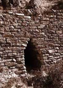
A dry masonry retaining wall with
a scupper culvert
Figure 2.1: Comparison of retaining wall types*
|
WALL TYPE |
MAXIMUM SAFE HEIGHT |
WIDTH: HEIGHT RATIO |
ADVANTAGES/LIMITATIONS |
|
Dry masonry |
4 metres |
1:1 to 0.6:1 |
Well drained; flexible; relatively low cost; low strength threshold |
|
Composite masonry |
8 metres |
0.75:1 to 0.5:1 |
Better drained than mortared masonry, but with reduced strength |
|
Mortared masonry |
10 metres |
0.75:1 to 0.5:1 |
Relatively easy to construct on steep terrain; cannot tolerate settlement; poor drainage |
|
Gabion |
10 metres |
Width = ½h + 0.5 |
Flexible without rupturing; tolerates poor foundations; well drained; relatively low cost for strength |
|
Reinforced earth |
8 metres |
Depends on design |
Reinforcing expensive or difficult to obtain; difficult to achieve tension |
|
Reinforced concrete |
10 metres |
Depends on design |
Relatively costly; requires advanced technical skills to build; poor drainage |
* Despite these general criteria, design must always be site specific rather than based on a 'typical' design.
Figure 2.1 compares the main types of retaining wall.
Integration with bio-engineering
Bio-engineering techniques should be used in conjunction with retaining walls, according to site characteristics, as follows:
· Protection of backfill.
· Protection from scour and undercutting of the foundations and sides.
· Flexible extension to the wall by planting large bamboos, shrubs or trees above the wall, increasing the catch function (refer to Sections 3.9 and 3.7 for details of these techniques).
Further information
There is an entire chapter on road retaining walls in TRL Overseas Road Note 16, Principles of low cost road engineering in mountainous terrain (chapter 11, Road retaining walls, pages 116 to 126). The design of retaining walls is also covered in most geotechnical engineering text books.
2.2 Revetment walls
Function
Revetment walls are constructed to protect the base of a slope from undermining or other damage, such as grazing by animals. They give only protection, not support, and are not used on large, unstable slopes, where substantial retaining structures may be required. Breast walls are normally considered to be types of revetment.
Sites
Along the base of inherently stable cut slopes where seepage erosion can destabilise the base of large slopes; along the foot of abandoned spoil tips which have reached their angle of repose; along the foot of large fill sites.
Practical features
· Excavate a foundation at the foot of the slope until you find a sound layer to build on.· Construct walls of freely drained materials wherever possible, such as dry stone masonry or gabions.
· If using cement-bound masonry, include weep holes to drain water from behind the wall and reduce hydrostatic pressure. Weep holes should have a minimum width of 75 mm, slope downwards, and be constructed every one metre along and up the wall. There should be a line of weep holes along the wall at the lowest point at which it can be drained.
· The back face should be vertical; the front face should slope back at the rate of 330 mm horizontally per metre of height (a gradient of 3:1);
· The ends of the wall should turn in to meet the slope, and should be raised about 250 mm: water falling on them will then run down over the wall and not scour the ends.
· If there is a risk of people or animals damaging the top of a dry stone wall, provide a capping beam of cement-bound masonry.
· Once the wall is complete, finish backfilling behind it and compact the fill thoroughly at a steep angle (at least 30°) to rejoin the original slope as high up as possible; plant into the fill as soon as you can.
Figure 2.2: A guide to the dimensions of dry masonry retaining walls on different slopes
|
SLOPE |
WALL HEIGHT |
BASE WIDTH |
TOP WIDTH |
|
30 - 35° (58 - 70%) |
1.5 - 2.0 m |
1.25 - 1.5m |
0.75 m |
|
35 - 40° (70 - 84%) |
2.0 - 2.5 m |
1.5 - 2.0m |
0.75 - 1.0 m |
|
40 - 45º (84 - 100%) V |
2.5 - 3.0 m |
2.0 - 2.3 m |
1.0 m |
|
SPECIAL FEATURES OF DRY MASONRY RETAINING WALLS · Careful design of dry masonry retaining walls can make them highly effective. · Lay the foundations back into the slope at 1v:3h. · Dress all stone (if it is rounded) into rectangular blocks. · Lay stones so that they are tied into the slope, so that only the small ends, not long sides, are at the face of the wall. · Overlap all joints. · Use stones as large as possible. If mainly small stones are available, use large ones at least every one metre to improve the tying. · Keep the angle of the foundations (1v:3h) with each layer of stone. The outer face of the wall will automatically come to 1h:3v if this is done. · Use flatter stones for the top layer. Cover the top of the retaining wall with soil or build a bound masonry band along the top to stop it unravelling. · Dry walls co-exist with, and are strengthened by plant roots. Encourage or plant vegetation. · Use the dimensions in Figure 2.2 for dry stone retaining walls, depending on slope angle. |
|
SPECIAL FEATURES OF GABION CONSTRUCTION Gabions have many possible functions, including their use in toe walls, revetments and retaining walls. They have special properties of strength, flexibility and free drainage. Practical features · The normal width to height ratio is: width = ½ height + 0.5 · Ensure drainage is provided from the lowest point of the foundations · Use heavily galvanised high-grade steel wire complying with the latest Nepal Standard. · Mesh should be, either a heavily galvanised mild steel or a triple-twist hexagonal mesh (i.e. 1.5 complete turns), nominally of 100 mm width and 120 mm length. · Panel frames should be made using 8 SWG wire, and mesh should be of 10 SWG wire. · Special attention must be paid to binding the boxes together along the seams (selvedging). · Wire all gabion boxes together using 12 SWG wire, allowing an additional 5% of wire for binding and tying. · During construction, add four or five cross-trusses (of 10 SWG wire) per square metre in each horizontal direction. · Ensure that the minimum dimension of all stones is larger than the wire mesh size. · Stones should be tabular and angular. · All stones should be carefully and densely packed, not just the facings. · Wire the lids down with additional wire of 12 SWG. · Backfill behind the gabion structure with a filter blanket to improve drainage. |
Integration with bio-engineering
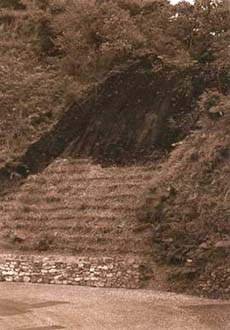
A revetment toe wall is protected
by grasses planted on the slope above
Bio-engineering techniques should be used in connection with revetment and toe walls as follows:
· Protection of backfill.
· Protection from scour and undercutting of the foundations and sides.
· Flexible extension above the wall by the use of large bamboo or shrub and tree planting, increasing the catch function: refer to Sections 3.9 and 3.7 for details of these techniques.
Further information
Revetments are covered in TRL Overseas Road Note 16, Principles of low cost road engineering in mountainous terrain (page 136), with typical design diagrams given on page 137.
2.3 Prop walls/Dentition
Function
The term 'prop wall' also covers support walls and dentition. On very steep cut slopes, prop walls are used to support blocks of harder rock where they are underlain by softer rock bands. Where differential weathering occurs due to variations in adjacent strata, large segments of slope can become destabilised by a soft rock band eroding away underneath it. This presents two options: either remove all the material above or support it with a prop wall.
Prop walls do not usually offer total support to the full weight of all slope material above. Rather, they stop the erosion of softer bands below harder bands supported on them.
Sites
Only on steep cut slopes. Anywhere that a large slope-trimming job can be avoided by installing a relatively small wall. This technique is particularly useful in bands of alternating hard and soft rocks, such as are common in the Churia ranges.
Practical features
· Excavate a foundation on a band of rock that is as hard as possible: this must be underneath the band that is being replaced by the prop wall and must show evidence of much greater resistance to erosion.· Using dressed stones and a cement: sand mixture of 1:4 or 1:3, build a cement masonry wall following the line of the slope.
· For sections less than 2 metres high only, use dry stone masonry built with well-dressed stones.
· In cement-bound masonry, weep holes should be at least 75 mm in diameter, sloping downwards and should be installed every 500 mm (horizontally as well as vertically); they must also be included in the lowest level of masonry.
· Normally, the bound masonry wall should be no more than 500 mm thick; if support deeper than this is required, it can be provided by careful dry stone packing behind the masonry wall. There must be no cavities allowing collapse of even very small areas behind the wall.
· When the lower surface of the material to be supported is reached, it is important to pack in the stones and mortar very tightly; the whole wall is useless if the last millimetre is not solidly completed.
Integration with bio-engineering
Prop walls are usually used to support bands of harder strata and so there is usually a limited scope for close integration with bio-engineering techniques. However, where conditions give rise to a need for additional protection, bio-engineering techniques should be used as follows:
· Protection from scour and undercutting of the foundations and sides.
Further information
Prop walls are covered in TRL Overseas Road Note 16, Principles of low cost road engineering in mountainous terrain under retaining structures (chapter 11, pages 116 to 126 and revetments (pages 136 and 137).
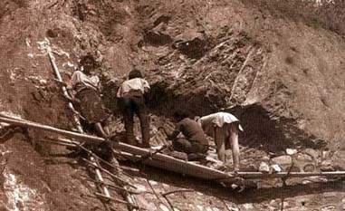
Constructing a cement masonry
dentition wall to prevent undercutting of the upper part of a steep cut slope in
differentially weathered
gneiss
2.4 Check dams
Function
Check dams are simple physical constructions to prevent the downcutting of runoff water in gullies. They ease the gradient of the gully bed by providing periodic steps of fully strengthened material. Check dams are designed to accept an active pressure if it applied in the future, while permitting a safe discharge of water (and perhaps debris) via a spillway.
Sites
Any loose or active gully. In any rill that threatens to enlarge. In general, anywhere on a slope where there is a danger of scour from running water.
Practical features
· Choose locations for the check dams so that the maximum effect can be achieved using the minimum possible volume of construction. Refer to the box on the spacing of check dams.· Excavate a foundation in the gully bed until you find a sound layer to build on. The base of the dam should be at least 660 mm thick if it is one metre high; for every additional metre of height, add a further 330 mm to the width.
· Construct the check dam using the best-drained and most cost-effective materials. If possible, use dry stone masonry or gabions to improve drainage. If this will not work, use concrete-bound mortar.
· If using concrete-bound masonry, include weep holes to drain water from behind the check dam and reduce hydrostatic pressure.
· The ends of the dam should be keyed right into the gully sides and should be raised at least 250 mm to form a central spillway or notch: this ensures that water coming over the dam will then run down the middle and not scour the ends.
· An apron must be provided below the dam to ensure that energy is dissipated and that flow continues in the centre of the gully below the check dam.
· If there is a risk of people or animals damaging the top of the dam, or if it is in a gully likely to take a large flow of water, point the top layer with cement mortar.
· Once the construction of the check dam is completed, backfill behind the wings and sides, and compact the fill thoroughly.

Small check dams at frequent
intervals are effective, even in very steep gullies
|
SPACING OF CHECK DAMS Check dams should normally be placed where: · they protect weak parts of a gully from scour; In most cases, gullies are so irregular that the spacing of check dams will be determined by ground conditions. However, if the gully is sufficiently uniform, the spacing of check dams can be determined using the relationship devised in 1973 by Heede and Mufich. This states that where X = check dam spacing in metres, K = 0.3 when tanS The effective height (HE) has to be estimated by the engineer on site. It is a function of the foundation conditions and the construction material used. The height should normally be maximised to reduce the number of check dams required. |

Integration with bio-engineering
Bio-engineering techniques should be used in connection with check dams as follows:
· Protection of backfill and gully floor above check dam.
· Protection from scour and undercutting of the foundations and sides.
· Construct live check dams between civil check dams, to reduce water velocity in the gully and improve stability (refer to Section 3.12); or line the gully bed with vegetated stone pitching (refer to Section 3.14 for details of this technique).
Further information
Check dams are discussed in TRL Overseas Road Note 16, Principles of low cost road engineering in mountainous terrain (page 108), with typical design diagrams given on pages 110 and 111.
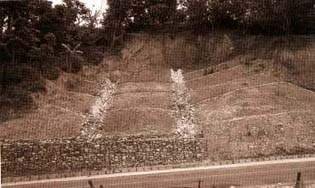
Stone-pitched surface drains on a
wet landslide
scar
2.5 Surface and sub-surface drains
Function
Surface drains are installed in the surface of a slope to remove surface water quickly and efficiently. Surface-water drains often use a combination of bio-engineering and civil engineering structures.
Cascades are surface drains designed to bring water down steep sections of slope.
Sub-surface drains are installed in the slope to remove ground water quickly and efficiently. In practice they can be installed to a maximum of 1.0 to 1.5 metres (although the design depends on site conditions). Sub-surface drains are usually restricted to civil engineering structures, and do not normally use bio-engineering measures. However, bio-engineering techniques can be used to strengthen the slope around the drain.
Sites
Any site less than 35°. Certain drain types can be used on slopes up to 45° (e.g. drains constructed using gabion wire or concrete-bound masonry). Cascades are normally used on slopes steeper than 45°.
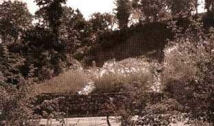
The same site, two years later,
following establishment of the protective grass cover between the drains
Figure 2.3: Surface drains and cascades, and sub-surface drains: design and integration with bio-engineering (all drainage systems are assumed to be dendritic)
|
DRAIN TYPE |
| | | |
|
STRUCTURE |
BIO-ENGINEERING |
MAIN SITES |
ADVANTAGES |
LIMITATIONS |
|
Unlined natural drainage system (rills and gullies already developed on bare surfaces). |
Grasses in the rills and gullies, and grasses and other plants on the sides. |
Existing landslide scars and debris masses. |
By far the cheapest form of surface drain. Rapid drainage is assured. |
There is a risk of renewed erosion in exceptionally heavy rain in weak materials. |
|
Unlined earth ditch system. |
Grasses and other plants on sides and between feeder arms. |
Slumping debris masses on slopes up to 45°, where the continued loss of material is not a problem (e.g. in debris masses well below a road, draining straight into large rivers). |
By far the cheapest form of surface drain. |
There is a serious erosion hazard, especially on steep main drains, so this type should be used only where further erosion is not a problem. Leakage into the ground may also occur. |
|
Unbound dry stone system of ditches. |
Grasses between stones (as vegetated stone pitching), and grasses and other plants on sides and between feeder arms. |
Almost any site, however unstable, where the ground is firm enough to hold stone pitching and the flow of water is not too excessive for this construction technique. |
A low-cost drain type. Strong and very flexible. These two features make it good on unstable slopes. |
A membrane of thick, black polythene may be required to stop leakage back into the ground. |
|
Bound cement masonry ditch system. |
Grasses and other plants on sides and between feeder arms. |
Only on stable slopes with suitable material for good foundations. |
A strong structure for heavy discharges. |
Relatively high cost. Very inflexible, so there is a high risk of cracking and failure due to subsidence and undermining. |
|
Wire bolster cylinders (herringbone pattern). |
Grasses and other plants on sides and between feeder arms. |
Almost any site, however unstable, without excessive amounts of stone, but where the ground is firm enough to hold the structure. The drainage discharge should not be excessive. |
A medium-cost shallow type of drain. Very strong and flexible, which makes it good for unstable slopes. |
A membrane of thick, black polythene may be required to stop leakage back into the ground. |
|
Open gabion ditch system. |
Grasses and other plants on sides and between feeder arms. |
Almost any site, however unstable, where the ground is firm enough to hold a relatively big structure, and where a large volume of discharge is possible. |
A large and high-cost type of drain. Very strong and flexible, which makes it good for unstable slopes. |
A membrane of thick, black polythene may be required to stop leakage back into the ground. |
|
CASCADES | ||||
|
Dry stone cascade. |
Grasses and other plants along the sides. |
Any slope section steeper than 50° where foundations are adequate and discharge is relatively low. |
A low-cost form of cascade with a degree of flexibility. |
A membrane of thick, black polythene may be required to stop leakage back into the ground. |
|
Mortared masonry cascade. |
Grasses and other plants along the sides. |
Very stable slope sections steeper than 45°, where foundations are very good. |
A strong structure for heavy discharges. |
Relatively high-cost and inflexible cascade type, so there is a high risk of cracking and failure due to subsidence and undermining. |
|
Gabion cascade. |
Grasses and other plants along the sides. |
Any slope section steeper than 45°, where foundations are adequate and discharge is likely to be high. |
Very strong and flexible, which makes it good for unstable slopes. |
A relatively large and high-cost cascade type. A membrane of thick, black polythene is required to stop leakage back into the ground. |
|
Concrete cascade. |
Grasses and other plants along the sides. |
Very stable slope sections steeper than 45°, where foundations are very good. |
A very strong structure for the heaviest discharges. |
Very high-cost and inflexible cascade type. The risk of cracking and failure due to subsidence and undermining is partly offset by the innate strength of the construction. |
Figure 2.3: Surface drains and cascades, and sub-surface drains: design and integration with bio-engineering (all drainage systems are assumed to be dendritic) continued
|
DRAIN TYPE |
| | | |
|
STRUCTURE |
BIO-ENGINEERING |
MAIN SITES |
ADVANTAGES |
LIMITATIONS |
|
SUB-SURFACE DRAINS | | | | |
|
French drain system (perforated pipe of durable, high grade black polythene, 150 mm diameter with approximately 40 holes of 5 mm per metre) in a drainage medium of aggregates). Drain can be made more resistant to disruption by building it in a casing of gabion. |
Grasses and other plants along the sides and between feeder arms. |
Almost any site, however unstable, where the ground is firm enough to hold the structure and the flow of water is not too excessive for this construction technique. |
A relatively low-cost and common sub-surface type of drain. Very flexible, which makes it good for unstable slopes. |
A membrane of permeable geotextile should be used. If the flow is too great, piping may occur underground. The outfall must be monitored to check that the drain is functioning, but the hidden nature of the drain means that this cannot always be fully ascertained. |
|
Site-specific design of drain to pick up seepage water. An open ditch or a drain with a flexible gabion lining is preferred. |
Plant grasses and other species along the sides. |
Any slope with obvious seepage lines. |
Specific drains can be designed for any site, leading to the optimum collection of water. |
Great care is needed to ensure all seepage water is trapped by the drain. Movement in the slope may affect this. |
|
Deep surface drain types (deeper versions of the surface drains described above, designed to catch shallow ground water seepage). |
As for each surface drain type described above. |
As for each surface drain type described above. |
Open drains allow easy cleaning and repair, as well as monitoring of effectiveness. |
The usual practical maximum depth is about 1.5 metres. Special care must be used to allow water to seep into the drains. |
Practical features
· Always design drainage systems to run along natural drainage lines. Choose locations for the drains so that the maximum effect can be achieved using the minimum possible volume of construction.· Always ensure that drain outfalls are protected against erosion.
· Only use a rigid geometrical pattern of drains on newly formed fill slopes where there are no clear natural drainage lines.
· Excavate a foundation until a sound layer to build on is located. Drains must be well founded like all other civil structures.
· Run main drains straight down the slope. Feed side drains in on a herringbone pattern.
· Never use contour drains: these block very easily and are also highly susceptible to subsidence. A blocked or cracked drain can create terrible damage as a result of concentrated water flow.
· Design and construct the drains in such a way that water can enter them easily on the higher side but not seep out on the lower side. Use weep holes and thick (³ 20 gauge), black polythene membranes carefully to achieve this.
· A flexible design is usually an advantage. Concrete masonry can be easily cracked by the slightest movement in the slope, and then leakage problems result.
· If there is a risk of people or animals damaging the drain, make sure that the construction is strong enough (e.g. use gabion rather than dry stone construction).
· Once the drain is completed, backfill around it and compact the fill thoroughly.
· Apply appropriate bio-engineering measures to enhance the effectiveness of the drain.
· Where the site requires deeper drainage and the machinery is available, drains can be drilled into the slope.
· Figure 2.3 gives comparison details of the main drain and cascade types.

A gabion cascade in heavy rain.
This type of structure can transport large volumes of water down steep slopes
without damage
Further information
Surface drainage on slopes is covered on pages 136 to 139 of TRL Overseas Road Note 16, Principles of low cost road engineering in mountainous terrain.
Sub-surface drainage on slopes is covered on pages 139 to 140 of TRL Overseas Road Note 16, Principles of low cost road engineering in mountainous terrain.
2.6 Stone pitching
Functions
A slope is armoured with stone pitching. This gives a strong covering. It is freely drained and will withstand considerable water velocities.
Note that in Section 3.14, among the bio-engineering techniques, full details are given of vegetated stone pitching: that is a stronger form of stone pitching, with emphasis given to its strengthening by vegetation.
Sites
Any slope up to 35°. This technique is particularly useful on slopes with a heavy seepage problem, in flood-prone areas or where vegetation is difficult to establish, such as in urban areas. It is also useful on gully floors between check dams and for scour protection by rivers.
Materials
· Boulders;
· Tools for digging and for dressing stones.
The largest available stones should be used which permits pitching to be done effectively on the site. The stones used should have one large flat side, and should be of equal size and angularity.
Spacing
Stone pitching effectively gives a complete surface cover.
Construction steps
1. Prepare a sound slope before constructing the stone pitching; it must be free of loose debris and topsoil, and trimmed to an even surface.2. Bed the stones down well into the slope surface. Excavate as necessary to ensure an even upper surface to the stone pitching.
3. Build the stone pitching carefully, with the stones fitted together firmly, as if it is a dry masonry wall. Stones should be perpendicular to the slope, with the main point or narrow side down.
4. In drains and gullies, a rough surface can be left to retard water flow.
5. For further strengthening it is best to plant grasses or the hardwood cuttings of shrubs through the stone pitching (see below and Section 3.14).
6. Other options for strengthening are either to use a gabion mattress (of 0.3 to 0.5 metre thickness) instead of dry stone pitching; or to use cement mortar (but this can impede drainage).
|
WHY YOU SHOULD AVOID USING CUT-OFF DITCHES OR CATCH DRAINS ABOVE CUT SLOPES Cut-off ditches, otherwise known as cut-off drains or catch drains are: · almost certain to become Mocked; A cut-off ditch becoming blocked or cracked is a common cause of a landslide or the severe erosion of a cut slope in Nepal. Damage to a cut slope can be considered the usual outcome of the installation of a cut-off ditch. This warning applies to all surface ditches that are out of sight of the road, and therefore they are best avoided unless there is no alternative. Water should be brought down the slope along its natural course, protected with vegetation and civil structures as required, and if necessary carried into the nearest roadside ditch by a cascade. Localised damage can then be seen and repaired as soon as it occurs. |
Integration with bio-engineering
For the best effects, bio-engineering techniques should be used in connection with stone pitching as follows.
· Strengthening of stone pitching: plant grass slips in the gaps between stones: see Section 3.14.· Increased strengthening of stone pitching: insert live cuttings of shrubs into the gaps between stones: see Section 3.14.
Maintenance
If stones are displaced, the pitching should be repaired as soon as possible. Otherwise the maintenance depends on the type of bio-engineering used (refer to the relevant part of Section 5 for details).
Main advantages
Stone pitching forms a strong and long-lasting method of reinforcing a slope surface and stopping gully development.
Main limitations
Stone pitching is relatively expensive in comparison with bio-engineering measures such as brush layers.
2.7 Wire Bolster Cylinders
Function
Wire bolster cylinders (in cross-section, a gabion tube of 300 mm diameter filled with stone) are laid in shallow trenches across the slope. They prevent surface scour and gullying (by reinforcing and fulfilling an intermittent armouring function), and provide shallow support. Bolsters can be laid in two ways: (1) along the contour; or (2) in a herringbone pattern (¬¬¬¬¬) to double as a surface drainage system.
Sites
On most long, exposed slopes between 35° and 50° where there is a danger of scour or gullying on the surface. Contour bolsters are used on well drained materials; slanted (herringbone pattern) bolsters are used on poorly drained material where there is a risk of slumping.
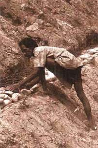
Constructing a wire bolster (see
construction step 5, overleaf)

Completed wire bolster cylinders
on a steep colluvial slope
Materials
· Woven gabion panels;· 16 mm rebar or high yield steel rod cut into 2 m lengths;
· Boulders:
for contour bolsters, angular,
smallest dimension > 100 mm;
for herringbone bolsters, rounded,
smallest dimension > 100 mm;
· Tools for digging trenches and for working with gabion wire;· Sledge hammers.
· For herringbone bolsters, thick (³ 20 gauge), black polythene sheet to line the trenches.
Gabion bolster panels are normally 5 m × 1 m. Where larger bolsters are required 5 m × 2 m panels can be woven. They are made on a conventional gabion weaving frame but with a smaller mesh than usual: this is normally 70 × 100 mm, triple twist. Heavy coated 10 SWG wire is used for the border and 12 SWG for the mesh.
Spacing
Contour bolsters are normally spaced as follows,
slope < 30°: 2000 mm centres;
slope 30 - 45°: 1500 mm centres.
Herringbone bolsters are placed at 1500 mm centres.
Construction steps (contour bolsters)
1 Trim the area to be treated to an even slope with no small protrusions or depressions which will interfere with the bolsters.2 Starting about 2 metres from the bottom of the slope, mark out a contour line across the slope with the aid of a spirit level.
3 Dig a trench along the line: the trench should be about 300 mm wide and 300 mm deep (Figure 2.4; a).
4 Lay a gabion bolster panel lengthways along the trench: make sure the edge of the panel on the lower side is flush with the edge of the trench.
5 Fill the bolster with stones larger than the mesh size (Figure 2.4; b, c).
6 Fold the upper edge of panel over the stones and join it to the lower panel edge. Leave a 100 mm flap from the upper edge extending over the lower edge (Figure 2.4; d).
7 Join abutting bolsters: form the bolsters into a continuous line across the slope and close the extreme ends with wire.
8 Backfill the material around the bolsters, compact it and clean away surplus debris.
9 Drive steel bars into the ground at right angles to the slope every 2 metres along the bolsters. Position them immediately below and touching the bolsters, and drive them in far enough so that they cannot be pulled out by hand (Figure 2.4; e).
10 Cover remaining site: repeat steps (2) to (9) up the slope at the spacing required until the area is covered.
11 Starting from the top of the slope, clean away surplus debris and make sure that backfill is complete and firm.
12 Implement bio-engineering works throughout the site.
Figure 2.4: Wire bolster
construction
Construction steps (herringbone bolsters)
1 The site to be treated should first be trimmed to an even slope: there should be no protrusions or depressions that will interfere with the bolsters; loose rocks should be removed if possible;2 Starting about 2 metres from the bottom of the slope, mark out the lines for the bolsters; they should be at 45° to the line of the slope and each slanting piece should normally be 5 metres long (although the design must be flexible to take individual site conditions into account).
3 Dig trenches along the lines, about 300 mm wide and 300 mm deep.
4 Lay a sheet of black polythene along the bottom and lower side, but not the higher side, of the trench.
5 Lay gabion bolster panels lengthways along the trenches. The edge of the panel on the lower side should be flush with the lower edge of the trench.
6 Fill the bolster with stones larger than the mesh size. Stones must not be packed carefully on top of each other as this reduces water flow: instead, they must be poured in from above and packed firmly but at random within the mesh.
7 Fold the upper edge of the panel over the stones and join it to the lower panel edge; at the end of the pattern, where the slanting lines meet, the bolster ends should be closed over with wire but not joined to adjacent patterns: this is so that each stack of V patterns can fail without affecting the pattern next to it.
8 Repeat steps 3 to 7 at 1.5 metre intervals, installing a series of bolsters up the slope.
9 Once the slanting lines are complete, dig a trench straight down the slope and install a 'vertical' bolster in it to collect water from the bottoms of each V, and run it to the base of the slope. Tie the herringbones or ribs to the spine.
10 Backfill the material around the bolsters, compact it and clean away surplus debris as necessary.
11 Drive mild steel bars into the ground at right angles to the slope every 2 metres along the bolsters: they should be positioned immediately below and touching the bolsters, and should be driven in far enough that they cannot be pulled out by hand.
12 Implement bio-engineering works throughout the site.
Integration with bio-engineering
The spaces between the bolsters should be treated with appropriate bio-engineering as soon as the subsequent rains have broken, as follows:
· Between wire bolster cylinders: plant shrub and small tree seedlings at 1000 mm centres throughout the slope treated, according to site characteristics and as determined by the instructions in Section 1.2.· If a more complete surface protection is required, the surface can be planted or seeded with grass between the wire bolster cylinders, using the techniques described in Sections 3.1 to 3.5, according to the site requirements described in Section 1.2.
Maintenance
Maintain the bio-engineering works according to the needs of the particular treatment used.
If rills develop between the bolsters and threaten to undercut them, small-scale stone dentition should be used to support undermined places and stop scour erosion. In extreme cases, fully stone-lined gullies can be made between bolsters in order to shed large amounts of accumulated runoff without damaging the slope.
Main advantages
Bolsters form the strongest and longest-lasting method of armouring a slope surface and preventing gully development.
Main limitations
Bolsters are relatively expensive in comparison with bio-engineering measures such as brush layers.
2.8 Other civil engineering techniques
Wire netting
Function
Wire netting (usually gabion wire mesh) is spread over the surface of a rocky slope. This can be carried out to reduce the shedding of rock debris and slow the degradation of the surface.
Sites
Slopes composed of hard rock with a degree of fragmentation leading to the occasional shedding of debris particles larger than about 100 mm.
Comments
The main difficulty with this technique is fixing the wire mesh to the face of the slope. This is normally done by hammering steel pegs into rock cracks or by cementing them into depressions. If this is done satisfactorily, then it can be a very robust measure.
If the slope has not been trimmed well in advance, the accumulation of loose boulders behind weakening wire netting could release a bigger and more dangerous load in one go, rather than a gradual shedding of individual boulders. But with a good maintenance regime this technique could be used to advantage.
Gunite (shotcrete)
Function
Gunite is a cement-stabilised aggregate sprayed on to a wire mesh slope covering. It can be used for surface armouring and to bind together the surface of weathered and fractured rock slopes.
Sites
This technique has potential on steep (> 50°) cut slopes less than about 30 metres in height.
Comments
This technique has been used successfully in Hong Kong and Malaysia. The main limitation is the difficulty of ensuring slope drainage through the covering, even when numerous weep holes are provided: it is generally considered to be inappropriate on slopes with high groundwater seepage rates, such as are common in Nepal. The expense is also a limiting factor.
Chunam
Function
Chunam is a lime-based plaster applied as a slurry across the surface of a slope. It waterproofs and supports the immediate surface, armouring against scour of the surface and weathering of the material below. It can be reinforced using wire mesh already attached to the surface.
Sites
This technique has potential on steep (> 50°) cut slopes less than about 30 metres in height.
Comments
This technique has been successful in limited areas only. It is essential to install drainage or weep holes, sloping towards the outside of the material. Even with these, many surfaces have failed when treated with chunam because too much water has percolated behind the surfacing from higher up the slope and it has flaked away from the less weathered material behind. The best successes might be achieved in naturally dry sites, where hard chunam facings can stop surface erosion during heavy rains.
Cement slurry
Function
A watery cement slurry is poured into the ground. It percolates along pores and gaps in the material. When it sets, it binds the material together and increases the cohesive strength. The main engineering function is to reinforce.
Sites
This technique has potential in highly permeable debris materials, such as colluvium with a low proportion of fines.
Comments
There are no records of the widespread use of this technique in Nepal, but it has been used occasionally on colluvial slopes above roads. It is probably only worth using on the very porous materials described above, where there is adequate void space to absorb a critical quantity of slurry. Its best application is to reinforce material immediately upslope from a retaining structure which is considered too weak, such as a gabion wall which has bulged: in this situation, it may avoid the necessity of replacing one threatened structure with a stronger one. It could also be used in a purpose-designed situation, where there is inadequate space to construct a wall of the desired thickness, and where cement stabilisation of the retained debris can increase the factor of safety satisfactorily. In emergencies, it might be used shortly before the start of the monsoon rains, when there is not enough time to build a normal structure.
Reinforced earth
Function
A proprietary or purpose-designed material is laid at intervals into debris, which is built up in layers to form a slope of earth strengthened with the reinforcing material. The result is intermediate in strength between a straightforward fill slope and a retaining structure. The main engineering function is to reinforce.
Sites
This technique is best used on fill slopes, where the design angle is relatively low and the major disturbance involved in construction can be accomplished more easily.
Comments
There are various proprietary systems of reinforced earth, but there are no records of them being tried for slope stabilisation in Nepal. A form of earth reinforcement could be undertaken using a material such as gabion mesh laid into the slope at intervals as it is backfilled. However, reinforced earth systems present complex slope stability calculations, and the standard retaining structures are preferable in most cases.
Further information
Reinforced earth structures are covered in TRL Overseas Road Note 16; Principles of low cost road engineering in mountainous terrain (page 122), with typical design diagrams given on page 120.
Soil nailing
Function
Tensile strengthening is added to the slope in the form of steel bars inserted into the soil (or surface layers). Insertion is possible to a maximum depth of about 5 metres.
Sites
Any slope that is liable to creeping planar mass failures and where access for machinery is feasible. It is not effective against erosion or many shear failures.
Comments
There are two main methods. One uses a procedure of drilling and grouting, and the other hammers the nails in, normally using a mechanical percussion device. Both have advantages in certain situations, but both require machinery to gain access to the slope. The high cost of the technique makes its usefulness in Nepal dubious compared with the established systems of slope stabilisation.
Further information
Information is available from the companies offering proprietary systems of soil nailing, and their agents. No proven examples of this technique are known in Nepal.
|
| ||||||||||||||||||||||||||||||||||||||||||||||||||||||||||||||||||||||||||||||||||||||||||||||||||||||||||||||||||||||||||||||||||||||||||
Roadside Bio-Engineering - Site Handbook (DFID, 1999, 160 p.)
Section Three - Bio-engineering techniques
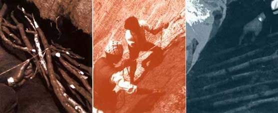
Figure
This section gives details of the design and construction of the main bio-engineering systems used for stabilising slopes and controlling erosion. These are:
· grass planting, seeding and turfing (Section 3.1 to 3.6);· shrub and tree planting and seeding (Sections 3.7 and 3.8);
· large bamboo planting (Section 3.9);
· brush layering (Section 3.10);
· palisades (Section 3.11);
· live check dams (Section 3.12);
· fascine constructions (Section 3.1 3);
· vegetated stone pitching (Section 3.14);
· jute netting: detailed information on its use and construction: standard mesh (Section 3.15) and wide mesh (Section 3.16);
· mulching: detailed information on the use of mulch as an aid to bio-engineering (Section 3.1 7);
· vegetated gabions (Section 3.18);
· live wattle fences (Section 3.19);
· hydro-seeding (Section 3.20).
Details of all of the civil engineering measures used in combination with these bio-engineering systems are given in Section 2.
3.1 Planted grass lines: contour/horizontal
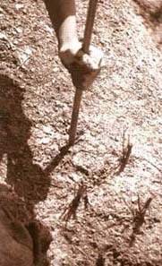
Planting grass lines. Use a
planting bar to make holes just big enough for the roots
Function
Grass slips (rooted cuttings), rooted stem cuttings or clumps grown from seed are planted in lines across the slope. They protect the slope with their roots and, by providing a surface cover, reduce the speed of runoff and catch debris, thereby armouring the slope. The main engineering functions are to catch, armour and reinforce.
Sites
Almost any slope less than 65°. This technique is mostly used on dry sites, where moisture needs to be conserved. It is most widely used on well-drained materials where increased infiltration is unlikely to cause problems. On cultivated slopes less than 35°, horizontal lines planted at intervals across the field can be used to avoid loss of soil and to help conserve moisture, as a standard soil conservation measure. Planted grass lines at intervals are essential if cultivation has to be carried out on slopes greater than 35°.

Place the grass into the hole,
taking care not to tangle the roots or have them curved back to the surface
Materials
· Grass plants raised in a nursery or cuttings obtained elsewhere;
· Short planting bars;
· Line string;
· Spirit level;
· Tape measure (30 metres);
· A means of transporting plants to site;
· Hessian and water to keep the roots moist;
· (Optional) Manure or compost.

Fill the soil in around them,
firming it gently with your fingers
SPECIES SUITABLE FOR PLANTED GRASS LINES: CONTOUR/HORIZONTAL
|
Local |
Botanical name |
Altitude |
Sites |
|
name |
|
range |
summary |
|
Amliso |
Thysanolaena maxima |
Terai -2000m |
Varied |
|
Babiyo |
Eulaliopsis binata |
Terai - 1500 m |
Hot and dry |
|
Dhonde |
Neyraudia reynaudiana |
Terai -1500 m |
Hot and dry |
|
Kans |
Saccharum spontaneum |
Terai - 2000 m |
Hot and dry; moist |
|
Katara khar |
Themeda species |
Terai - 2000 m |
Varied |
|
Khar |
Cymbopogon microtheca |
Terai - 2000 m |
Hot and dry; varied |
|
Khus |
Vetiveria lawsoni |
Terai - 1500 m |
Varied |
|
Narkat |
Arundo clonax |
Terai - 1500 m |
Hot and dry; varied |
|
Padang bans |
Himalayacalamus hookerianus |
1500 - 2500 m |
Moist |
|
Phurke |
Arunduella nepalensis |
700 - 2000 m |
Varied; stony |
|
Sito |
Neyraudia arundinacea |
Terai - 1500 m |
Varied |
|
Tite nigalo bans |
Drepanostachyum intermedium |
1000 - 2500 m |
Varied |
Spacing
Line spacing depends largely on the steepness of the slope.
Within rows: plants at 100 mm centres (except padang and tite nigalo bans, which should be spaced at 500 mm centres)
Row spacings:
slope < 30°: 1000 mm;
slope 30-45°: 500 mm;
slope > 45°: 300 mm.
Where this technique is used on agricultural land, a compromise must be reached between ease of cultivation and reduction of soil and water movement. A vertical interval of 2 metres or more is generally adequate.
Construction steps
1 Prepare the site well in advance of planting. Remove all debris and either remove or fill in surface irregularities so that there is nowhere for erosion to start. If the site is on backfill material, it should be thoroughly compacted, preferably when wet.2 Always start grass planting at the top of the slope and work downwards.
3 Mark out the lines with string, using a tape measure and spirit level. Make sure the lines run exactly as required by the specification, along the contour.
4 Split the grass plants out to give the maximum planting material. Trim off long roots and cut the shoots off at about 100 mm above ground level. Wrap the plants in damp hessian to keep them moist until they are planted. Remember that you will need two slip cuttings per drill (planting hole) if the grass is a fibrous rooting type (e.g. babiyo, kans, khar, phurke, etc.) but only one if it is rhizomatous (e.g. amliso, padang bans, etc.), and only one rooted stem cutting or seedling.
5 With a planting bar, make a hole just big enough for the roots. Place the grass into the hole, taking care not to tangle the roots or have them curved back to the surface. Fill the soil in around them, firming it gently with your fingers. Take care to avoid leaving an air pocket by the roots.
6 If compost or manure are available, scatter a few handfuls around the grasses. This is especially important on very stony sites, where compost or manure can help to improve early growth. You may have to incorporate it into the surface material to prevent it being washed off.
7 If it looks rather dry and there is no prospect of rain for a day or two, consider watering the plants by hand.
Maintenance
This normally involves:
Protection (check on Kartik 1);
Weeding (check on Shrawan 1, Bhadra 1 and Aswin 1);
Grass cutting (check on Poush 1).
Main functions
Contour grass lines catch material moving downslope. They also armour slopes on highly impermeable materials by retarding runoff and reinforcing slope materials.
Main limitations
Contour grass lines can increase the infiltration rate to the point of liquefaction on poorly drained materials, particularly on steeply sloping, fine-textured debris.
3.2 Planted grass lines: downslope/vertical
Function
Grass slips (rooted cuttings), rooted stem cuttings or seedlings are planted in lines running down the slope. They protect the slope with their roots, provide a surface cover and help to drain surface water. They do not catch debris. The main engineering functions are to armour, reinforce and drain. Using this technique, a slope is allowed to develop a semi-natural drainage system, gullying in a controlled way.
Sites
Almost any slope less than 65°. It is mostly used on damp sites, where moisture needs to be shed. It is also most widely used on poorly drained materials where an increase in infiltration can lead to liquefaction of the soil.
Materials
· Grass plants raised in a nursery or cuttings obtained elsewhere;
· Line string;
· Triangular set square or frame with a plumb line;
· Spirit level;
· Tape measure (30 metres);
· A means of transporting plants to site;
· Hessian and water to keep the roots moist;
· (Optional) Manure or compost.
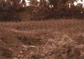
Vertical grass lines allow a slope
to develop a semi-natural drainage system, reducing infiltration and the
likelihood of liquefaction of the soil
Spacing
If the site is a newly cut slope, then a simple geometrical pattern can be used. The normal spacing is as follows:
Within rows: plants at 100 mm centres (except padang and tite nigalo bans, which should be spaced at 500 mm centres)Row spacings: 500 mm.
SPECKS SUITABLE FOR PLANTED GRASS LINES: DOWNSLOPE/VERTICAL
|
Local name |
Botanical name |
Altitude range |
Sites summary |
|
Amliso |
Thysanolaena maxima |
Terai - 2000 m |
Varied |
|
Babiyo |
Eulaliopsis binata |
Terai - 1500 m |
Hot and dry |
|
Dhonde |
Neyraudia reynaudiana |
Terai - 1500 m |
Hot and dry |
|
Kans |
Saccharum spontaneum |
Terai - 2000 m |
Hot and dry; moist |
|
Katara khar |
Themeda species |
Terai - 2000 m |
Varied |
|
Khar |
Cymbopogon microtheca |
Terai - 2000 m |
Hot and dry; varied |
|
Khus |
Vetiveria lawsoni |
Terai - 1500 m |
Varied |
|
Narkat |
Arundo clonax |
Terai - 1500 m |
Hot and dry; varied |
|
Padang bans |
Himalayacalamus hookerianus |
1500 -2500m |
Moist |
|
Phurke |
Arunduella nepalensis |
700 - 2000 m |
Varied; stony |
|
Sito |
Neyraudia arundinacea |
Terai - 1500 m |
Varied |
|
Tite nigalo bans |
Drepanostachyum intermedium |
1000 -2500m |
Varied |
However, if a gully system has already partly developed, then the spacing is defined naturally. Lines of grass should not be more than 500 mm apart if possible and, if ridges are bigger, a series of small lines in a chevron pattern (<<<<<) is required to protect gaps. Careful supervision is required on site to ensure that all planted lines follow the direction of natural fall.
Construction steps
1 Prepare the site well in advance of planting. Remove all debris and either remove or fill in surface irregularities so that there is nowhere for erosion to start.2 Always start grass planting at the top of the slope and work downwards.
3 Mark out the lines with string, using a tape measure. Use the spirit level, string and set square, or the frame to check the maximum line of fall. Make sure the lines run exactly as required by the specification, down the slope or drainage line.
4 Split the grass plants out to give the maximum planting material. Trim off long roots and cut the shoots off at about 100 mm above ground level. Wrap the plants in damp hessian to keep them moist until they are planted. Remember that you will need two slip cuttings per drill (planting hole) if the grass is a fibrous rooting type (e.g. babiyo, kans, khar, phurke, etc.) but only one if it is rhizomatous (e.g. amliso, padang bans, etc.), and only one rooted stem cutting or seedling.
5 With a planting bar, make a hole just big enough for the roots. Place the grass into the hole, taking care not to tangle the roots or have them curved back to the surface. Fill the soil in around them, firming it gently with your fingers. Take care to avoid leaving an air pocket by the roots. Mound the soil along the grass line, to encourage water to run mid way between the lines rather than close to the plant stems.
6 If compost or manure is available, scatter a few handfuls around the grasses. This is important on very stony sites, where it can help to improve early growth. You may have to incorporate it into the surface material to prevent it being washed off.
7 If it looks rather dry and there is no prospect of rain for a day or two, consider watering the plants by hand.
Maintenance
This normally involves:
Protection (check on Kartik 1);
Weeding (check on Shrawan 1, Bhadra 1 and Aswin 1);
Grass cutting (check on Poush 1).
If gullies develop, they must be controlled. If they become large enough to endanger the site, they must be checked with dry stone pitching and small check dams. If caught early enough, a few stones may be all that is required to create an armoured rill in which the runoff can safely pass. If allowed to grow too big, much more work will be required.
Main functions
Downslope grass lines provide the maximum amount of surface drainage by channeling runoff and minimising infiltration. They still armour against erosion and reinforce the slope.
Main limitations
On impermeable materials, runoff can become damaging. In drier sites, grass plants can suffer from drought due to the increased drainage. On some weak materials, rills can develop down the side of the plant line, damaging the grass slips and reducing their growth.
3.3 Planted grass lines: diagonal
Function
Grass slips (rooted cuttings), rooted stem cuttings or seedlings are planted in lines running diagon-ally across the slope. They armour the slope with their roots and by providing a surface cover. They have limited functions of catching debris and draining surface water. The main engineering functions are to armour and reinforce, with secondary functions to catch and drain. This technique offers the best compromise of the grass line planting systems in many situations.
Sites
Almost any slope less than 65°. It is mostly used on poorly drained materials where an increase in infiltration can lead to liquefaction of the soil. It is also useful on damp sites, where moisture needs to be shed. It should be used whenever there is doubt as to which grass line planting system should be used, as a result of uncertainties over site environmental characteristics or material properties.
Materials
· Grass plants raised in a nursery or cuttings obtained elsewhere;
· Line string;
· Tape measure (30 metres);
· Triangular set square or frame with a plumb line (optional);
· Spirit level (optional);
· A means of transporting plants to site;
· Hessian and water to keep the roots moist;
· (Optional) Manure or compost.
Spacing
If the site is a newly cut slope, then a simple geometrical pattern can be used. The normal spacing is as follows:
Within rows: plants at 100 mm centres (except padang and tite nigalo bans, which should be spaced at 500 mm centres)Row spacings: 500 mm.
However, if a gully system has already partly developed, then the spacing is defined naturally. Lines of grass should not be more than 500 mm apart if possible and, if ridges are bigger, a series of small lines in a chevron (<<<<<) or herringbone (¬¬¬¬¬) formation is required to protect gaps.
Construction steps
1 Prepare the site well in advance of planting. Remove all debris and either remove or fill in surface irregularities so that there is nowhere for erosion to start.2 Always start grass planting at the top of the slope and work downwards.
3 Mark out the lines with string using a tape measure. Make sure they run exactly as required by the specification, diagonally across the slope or towards drainage lines. It may help to use a spirit level and set square or frame to check the maximum line of fall.
4 Split the grass plants out to give the maximum planting material. Trim off long roots and cut the shoots off at about 100 mm above ground level. Wrap the plants in damp hessian to keep them moist until they are planted. Remember that you will need two slip cuttings per drill (planting hole) if the grass is a fibrous rooting type (e.g. babiyo, kans, khar, phurke, etc.) but only one if it is rhizomatous (e.g. amliso, padang bans, etc.), and only one rooted stem cutting or seedling.
5 With a planting bar, make a hole just big enough for the roots. Place the grass into the hole, taking care not to tangle the roots or have them curved back to the surface. Fill the soil in around them, firming it gently with your fingers. Take care to avoid leaving an air pocket by the roots.
6 If compost or manure is available, scatter a few handfuls around the grasses. If the site is very stony, this is important for improving early growth. You may have to incorporate it into the surface material to prevent it being washed off.
7 If it looks rather dry and there is no prospect of rain for a day or two, consider watering the plants by hand.
SPECIES SUITABLE FOR PLANTED GRASS LINES: DIAGONAL
|
Local name |
Botanical name |
Altitude range |
Sites summary |
|
Amliso |
Thysanolaena maxima |
Terai - 2000 m |
Varied |
|
Babiyo |
Eulaliopsis binata |
Terai - 1500 m |
Hot and dry |
|
Dhonde |
Neyraudia reynaudiana |
Terai - 1500 m |
Hot and dry |
|
Kans |
Saccharum spontaneum |
Terai - 2000 m |
Hot and dry; moist |
|
Katara khar |
Themeda species |
Terai - 2000 m |
Varied |
|
Khar |
Cymbopogon microtheca |
Terai - 2000 m |
Hot and dry; varied |
|
Khus |
Vetiveria lawsoni |
Terai - 1500 m |
Varied |
|
Narkat |
Arundo clonax |
Terai - 1500 m |
Hot and dry; varied |
|
Padang bans |
Himalayacalamus hookerianus |
1500 - 2500 m |
Moist |
|
Phurke |
Arunduella nepalensis |
700 - 2000 m |
Varied; stony |
|
Sito |
Neyraudia arundinacea |
Terai - 1500 m |
Varied |
|
Tite nigalo bans |
Drepanostachyum intermedium |
1000 - 2500 m |
Varied |
Maintenance
This normally involves:
Protection (check on Kartik 1);
Weeding (check on Shrawan 1, Bhadra 1 and Aswin 1);
Grass cutting (check on Poush 1).
Main functions
Diagonal grass lines armour and reinforce slopes effectively, and can also drain and catch material moving down the slope. This system appears to combine the best features of both horizontal and vertical planting in the majority of sites.
Main limitations
Where the specific advantages of contour or downslope planting patterns are critical, diagonal planting should not be used. On certain very weak materials, small rills can develop down the slope.
3.4 Planted grasses: random planting
Function
Grass slips (rooted cuttings), rooted stem cuttings or seedlings are planted at random on a slope, to an approximate specified density. They armour and reinforce the slope with their roots and by providing a surface cover. They also have a limited function of catching debris. This technique is most commonly used in conjunction with standard mesh jute netting, where complete surface protection is needed on very steep, harsh slopes. In most other cases, however, the advantages of one of the grass line planting systems (i.e. contour, downslope or diagonal) offer better protection to the slope.
Sites
Almost any slope less than 60° that allows grass planting. Normally used only on sites where jute netting (standard mesh) has already been applied. This implies slopes steeper than 45° and less than 15 metres in length, where moisture is not a serious problem.
Materials
· Grass plants raised in a nursery or cuttings obtained elsewhere;
· Short planting bars;
· A means of transporting plants to site;
· Hessian and water to keep the roots moist;
· (Optional) Manure or compost.
Spacing
Plants should be at an average of 100 mm centres (i.e. 100 plants per square metre). No gap should exceed 200 mm.
Construction steps
1 Apply the jute netting (standard mesh) well in advance of the monsoon, as described in Section 3.15. Start the grass planting as soon as the rains allow. If the site has not been treated with jute netting, prepare it well in advance of planting: remove all debris and either remove or fill in surface irregularities so that there is nowhere for erosion to start.2 Always start grass planting at the top of the slope and work downwards. Workers should stand on the pegs holding the netting, not on the netting itself.
3 Split the grass plants out to give the maximum planting material. Trim off long roots and cut the shoots off at about 100 mm above ground level. Wrap the plants in damp hessian to keep them moist until they are planted. Remember that you will need two slip cuttings per drill (planting hole) if the grass is a fibrous rooting type (e.g. babiyo, kans, khar, phurke, etc.) but only one if it is rhizomatous (e.g. amliso, padang bans, etc.), and only one rooted stem cutting or seedling.
4 With a planting bar, make a hole just big enough for the roots. Place the grass into the hole, taking care not to tangle the roots or have them curved back to the surface. Fill the soil in around them, firming it gently with your fingers.
5 Plant grasses at random over the surface, but aim for an average spacing of 100 mm centres (i.e. 100 plants per square metre). No gap should be greater than 200 mm.
6 If compost or manure is available, scatter a few handfuls around the grasses.
7 If it looks rather dry and there is no prospect of rain for a day or two, consider watering the plants by hand.
Maintenance
This normally involves:
Protection (check on Kartik 1);
Weeding (check on Shrawan 1, Bhadra 1 and Aswin 1);
Grass cutting (check on Poush 1).
Main functions
Random grass planting armours and reinforces slopes effectively. This is particularly the case when it is used in conjunction with standard mesh jute netting.
Main functions and limitations
Where the specific advantages of contour, downs-lope or diagonal planting patterns are critical, random planting should not be used.
SPECIES SUITABLE FOR PLANTED GRASSES: RANDOM PLANTING
|
Local name |
Botanical name |
Altitude range |
Sites summary |
|
Amliso |
Thysanolaena maxima |
Terai - 2000 m |
Varied |
|
Babiyo |
Eulaliopsis binata |
Terai - 1500 m |
Hot and dry |
|
Dhonde |
Neyraudia reynaudiana |
Terai - 1500 m |
Hot and dry |
|
Kans |
Saccharum spontaneum |
Terai - 2000 m |
Hot and dry; moist |
|
Katara khar |
Themeda species |
Terai - 2000 m |
Varied |
|
Khar |
Cymbopogon microtheca |
Terai - 2000 m |
Hot and dry; varied |
|
Khus |
Vetiveria lawsoni |
Terai - 1500 m |
Varied |
|
Narkat |
Arundo clonax |
Terai - 1500 m |
Hot and dry; varied |
|
Phurke |
Arunduella nepalensis |
700 - 2000 m |
Varied; stony |
|
Sito |
Neyraudia arundinacea |
Terai - 1500 m |
Varied |
3.5 Grass seeding
Function
Grass is sown directly on to the site. It allows easy vegetation coverage of large areas. This technique is often used in conjunction with mulching and jute netting to aid establishment. The main engineering functions are to armour and, later, to reinforce.
Sites
Almost any bare site with slopes up to 45°. Grass seeding is mostly used on well-drained materials, where increased infiltration does not give rise to problems.
Materials
· A supply of a carefully chosen grass seed;
· Tools to scarify the surface to be sown;
· Mulch (cut plant material) or hessian sheeting to cover the seed once sown (see Section 3.17).
· On slopes of 30° to 45°, wide mesh jute netting will be required to hold the mulch in place on the slope (see Section 3.16).
SPECIES SUITABLE FOR GRASS SEEDING
|
Local name |
Botanical name |
Altitude range |
Sites summary |
|
Babiyo |
Eulaliopsis binata |
Terai - 1500 m |
Hot and dry |
|
Dhonde |
Neyraudia reynaudiana |
Terai - 1500 m |
Hot and dry |
|
Kans |
Saccharum spontaneum |
Terai - 2000 m |
Hot and dry; moist |
|
Katara khar |
Themeda species |
Terai - 2000 m |
Varied |
|
Khar |
Cymbopogon microtheca |
500 - 2000 m |
Hot and dry; varied |
|
Phurke |
Arunduella nepalensis |
700 - 2000 m |
Varied; stony |
|
Sito |
Neyraudia arundinacea |
Terai - 1500 m |
Varied |

In grass seeding, spread the seeds
or grass seed heads liberally over the slope. Ideally, the whole surface should
be very lightly covered in seed material
Construction steps
1 Well in advance of the date of sowing, prepare the site. Remove all irregularities likely to allow slumps or gullies and clean loose debris away.2 Immediately before sowing, scarify the surface of the slope. This means scratching the surface or carrying out basic cultivation to give a loose surface into which the germinating grass seeds can send their roots.
3 Start sowing from the top of the slope and work downwards. Spread the seeds or grass seed heads liberally over the slope. Ideally, the whole surface should be very lightly covered in seed material. An application rate of 25 grammes per square metre is normal.
4 Cover the seeds completely with a layer of mulch, made from cut herbs such as ban mara (Eupatorium adenophorum), or with hessian sheeting. A vegetation mulch is preferable. Wide mesh jute netting (150 mm × 500 mm mesh size) should be used to hold mulch on to the surface if the slope is greater than 30°.
Maintenance
This normally involves:
Protection (check on Kartik 1);
Weeding (check on Shrawan 1, Bhadra 1 and Aswin 1);
Grass cutting (check on Poush 1).
Main functions
Grass seeding armours surfaces effectively: it can be used to create an even cover over all surfaces. It reinforces slopes after a few years of growth.
Main limitations
This technique gives none of the structural advantages of grass slip planting. Plants take longer to develop from seeds than from slips. Very heavy rain in the days immediately after sowing can lead to seeds being washed off the slope, or to damage to the very small seedlings.
3.6 Turfing
Function
Turf, consisting of a shallow rooting grass and the soil it is growing in, is placed on the slope. A technique commonly used on gentle embankment slopes. Its only engineering function is to armour.
Sites
This technique can be used on any gently sloping site (less than 30°). It is normally used on well-drained materials, where there is a minimal risk of slumping
Materials
· Flat shovel with a sharp edge to cut the turf;
· Old khukuri to cut the turf to shape;
· Water to keep the turf moist;
· Wooden rammer (mungro);
· If the slope to be turfed is greater than about 25°, wooden pegs about 300 mm long and 30 mm in diameter will be required.
SPECIES SUITABLE FOR TURFING
|
Local name |
Botanical name |
Altitude range |
Sites summary |
|
Dubo |
Cynodon dactylon |
Terai - 1800 m |
Varied |
Construction steps (making turf)
Turf should be cut the same day as it is to be placed; if this is not possible, it should be kept very moist in a shady place. To cut the turf:
1 Mark out with lines the size and shape to be cut (300 mm square is easy to manage but 300 × 600 mm is better);2 Cut the sides of the shapes with a khukuri, to at least 50-mm depth;
3 Using a broad, flat shovel with a sharp edge, cut horizontally under the shapes and lift them out.
If the ground where the turf is to be taken from is hard and dry, it may be helpful to water it thoroughly the day before cutting.

Turfing provides instant surface
protection, as used on this road shoulder (the embankment has been treated with
grass lines and brush layering)
Construction steps (placing the turf)
1 Well in advance of the turfing operation, thoroughly smooth the surface to be covered. It is most important to obliterate all irregularities;2 If the slope to be turfed is a gravel-fill embankment, then a 50-mm layer of topsoil should be laid and compacted by hand;
3 Immediately before placing the turf, scarify the ground surface slightly and water it well if it is not already moist;
4 Place the turf, taking care to fit the pieces together with no gaps between. Use the khukuri to cut the pieces to shape;
5 If the slope is steeper than about 25°, wooden pegs should be hammered through the turf to stop it sliding;
6 Once the slope has been satisfactorily covered, compact the turf with the wooden rammer.
7 Finally, water the fresh turf thoroughly.
Maintenance
This normally involves:
Protection (check on Kartik 1);
Grass cutting (check on Poush 1).
Main functions
Turfing armours slopes: it gives a complete instant surface cover.
Main limitations
Turfing is relatively costly, and creates equal bare areas at the source of the turf, where erosion can start. For this reason its use needs to be restricted in hill areas. In addition, there is a discontinuity between the turf and the underlying material which, in extreme conditions, can give rise to gradual creep or a shallow planar failure. Because turfing has to be carried out using the small grass dubo, there are no higher plants to discourage animal tramping, so damage can be caused by this means.
3.7 Shrub and tree planting
Function
Shrubs or trees are planted at regular intervals on the slope. As they grow, they create a dense network of roots in the soil. The main engineering functions are to reinforce and, later, to anchor. In the long term, large trees can also be used for slope support.
Sites
This method can be used without adverse effects on almost any slope up to 30°. With care, it can be used on slopes between 30° and 45°. It can be used on any material and in any site.
Materials
· Plants raised in a nursery, usually as polypot seedlings;
· Tools to dig holes and a means of transporting the plants to site;
· (Optional) Compost.
Spacing
The spacing of plants is important. The main considerations are cost and the speed with which a full cover is required. In most bio-engineering sites a spacing of 1 × 1 metre is necessary, requiring 10,000 plants per hectare. Plants should be planted in off-set rows unless a different pattern is needed for specific bio-engineering requirements.
Construction steps
1 Prepare the site well in advance of planting. Remove all debris and remove or fill surface irregularities. If the site is on backfill material, thoroughly compact it, preferably when it is wet. Cut all weeds.2 If possible, dig pits for the shrubs or trees well in advance of the planting programme, but refill them the same day. Pits should be 300 mm deep and 300 mm in diameter if this is possible without causing excessive damage to the slope.
3 When the ground is wet enough to support reasonable growth, plant out the seedlings. The bigger the hole made, the better it is for the plant; but there must be a compromise between helping the plant and avoiding excessive disturbance to the slope.
4 Carefully remove the polypot by slicing it down the side with a razor blade or tear it carefully along the fold. Take care not to cut the roots.
5 Plant the seedling in the pit, filling the soil carefully around the cylinder of roots and soil from the polypot. Ensure there are no cavities. Firm the soil all around the seedling with gentle foot pressure.
6 If available, mix a few handfuls of well-rotted compost with the soil around the roots when you are backfilling the hole.
7 Remove any weeds around the plant. Add mulch around the seedling, but with a slight gap so that it does not touch the stem.
SPECIES SUITABLE FOR SHRUB AND TREE PLANTING
|
Local name |
Botanical name |
Altitude range |
Sites summary |
|
Shrubs |
| | |
|
Areri |
Acacia pennata |
500 - 1500 m |
Hot and dry; harsh |
|
Dhanyero |
Woodfordia fruticosa |
Terai - 1500 m |
Hot and dry; harsh |
|
Dhusun |
Colebrookea oppositifolia |
Terai - 1000 m |
Hot and dry; harsh |
|
Kanda phul |
Lantana camara |
Terai - 1750 m |
Hot and dry |
|
Keraukose |
Indigofera atroturpurea |
Terai - 2000 m |
Hot and dry; harsh |
|
Tilka |
Wendlandia puberula |
Terai - 1500 m |
Hot and dry; harsh |
|
Trees | | | |
|
Bakaino |
Melia azedarach |
Terai - 1800 m |
Hot and dry; harsh |
|
Chilaune |
Schima wallichii |
900 - 2000 m |
Varied; dry - moist |
|
Gobre salla |
Pinus wallichiana |
1800 - 3000 m |
Dry; varied |
|
Kalo siris |
Albizia lebbeck |
Terai - 1200 m |
Hot and dry; harsh |
|
Kbanyu (khosro) |
Ficus semicordata |
Terai - 2000 m |
Hot and dry; varied |
|
Khayer |
Acacia catechu |
Terai - 1000 m |
Hot and dry; harsh |
|
Lankuri |
Fraxinus floribunda |
1200 - 2700 m |
Varied; moist best |
|
Painyu |
Prunus cerasoides |
500 - 2400 m |
Varied/dry; stony |
|
Rani (khote) salla |
Pinus roxburghii |
500 - 1950 m |
Hot and dry; varied |
|
Rato siris |
Albizia julibrissin |
800 - 3000 m |
Varied and moist |
|
Seto siris |
Albizia procera |
Terai - 1350 m |
Moist |
|
Sisau |
Dalbergia sissoo |
Terai - 1400 m |
Varied |
|
Utis |
Alnus nepalensis |
900 - 2700 m |
Varied and moist |
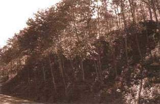
This eight-year old utis
plantation, raised from polypot seedlings, is established enough to reinforce
and anchor the roadside slope
Maintenance
This normally involves:
Protection (check on Kartik 1);
Weeding (check on Shrawan 1, Bhadra 1 and Aswin 1);
Thinning (check on Kartik 1, starting three years after site works).
Main functions
Planting shrubs and trees reinforces and anchors the slope by establishing a community of larger plants.
Main limitations
Seedlings take about five years to contribute significantly to slope strengthening. Care and protection are required in the first three years.
3.8 Shrub and tree seeding
Function
Shrub (or tree) seeds are applied directly to the site. This technique allows very steep, rocky and unstable slopes to be revegetated where cuttings and seedlings cannot be planted. There are two methods: (1) direct sowing and (2) broadcasting. In the first, seeds are placed individually, whereas the second involves throwing the seed all over the site. The main engineering functions are to reinforce and, later, to anchor.
Sites
Any steep, rocky or unstable sites. This technique is particularly useful on fractured rock slopes where normal planting cannot be done. Direct sowing can be practised on very steep slopes (i.e. up to about 60°) and it is rarely necessary to use this technique on slopes more gentle than 45°. Broadcasting seeds can be carried out on any slopes up to 45°, but is usually less successful on slopes steeper than 30°.
Materials
· A supply of the seeds to be sown;
· Small planting bars (if direct seeding).
Construction steps: direct seeding
The sowing of shrub seeds directly into the material of the site. Choose larger seeds such as areri or bhujetro.
1 In advance of the sowing programme, clear all very loose debris from the site.2 Start seeding from the top of the slope and move downwards. Make a small hole, a little bigger than the seed, using a planting bar.
3 Push the seed right into the hole and cover it with soil; or, if it is in a rocky crevice, check that it is right out of direct sunlight. Make sure that the seed coat is not damaged in this process.
Construction steps: broadcasting
The sowing of tree and shrub seeds by throwing them over the site. It is normal to choose small seeds such as khanyu or utis, although larger seeds can be used as well.
1 In advance of the sowing programme, clear all very loose debris from the site.2 Any smooth surfaces should be scarified to give a rough, looser surface for the seed to be held on and put roots into.
3 Throw the seeds on to the surface of the slope, ensuring that they do not blow away or slide down into concentrated masses in crevices and rills.
Spacing
Seeds are normally sown or broadcast to give a coverage of one plant every 250 mm, centre to centre. The actual seeding rate should be increased to three seeds for every plant required to give a reasonable survival rate.
Maintenance
This normally involves:
Protection (check on Kartik 1);
Weeding (check on Shrawan 1, Bhadra 1 and Aswin 1);
Thinning (check on Kartik 1, starting three years after site works).
SPECIES SUITABLE FOR SHRUB AND TREE SEEDING
Main species used for direct seeding
|
Local name |
Botanical name |
Altitude range |
Sites summary |
|
Shrubs |
| | |
|
Areri |
Acacia pennata |
500 - 1500 m |
Hot and dry; harsh |
|
Bhujetro |
Butea minor |
500 - 1500 m |
Hot and dry; harsh |
|
Keraukose |
Indigofera atroturpurea | |
Hot and dry; harsh |
Main species used for broadcasting
|
Local name |
Botanical name |
Altitude range |
Sites summary |
|
Shrubs |
| | |
|
Areri |
Acacia pennata |
500 - 1500 m |
Hot and dry; harsh |
|
Bhujetro |
Butea minor |
500 - 1500 m |
Hot and dry; harsh |
|
Keraukose |
Indigofera atroturpurea |
Terai - 2000 m |
Hot and dry; harsh |
|
Trees |
| | |
|
Bakaino |
Melia azedarach |
Terai - 1800 m |
Hot and dry; harsh |
|
Gobre salla |
Pinus wallichiana |
1800 - 3000 m |
Dry; varied |
|
Khanyu (khosro) |
Ficus semicordata |
Terai - 2000 m |
Hot and dry; varied |
|
Khayer |
Acacia catechu |
Terai - 1000 m |
Hot and dry; harsh |
|
Rani (khote) salla |
Pinus roxburghii |
500 - 1950 m |
Hot and dry; varied |
|
Sisau |
Dalbergia sissoo |
Terai - 1400 m |
Varied |
|
Utis |
Alnus nepalensis |
900 - 2700 m |
Varied and moist |
Main functions
Seeding shrubs and trees reinforces and anchors any slope, however rocky, by establishing a community of larger plants.
Main limitations
Seedlings take about five years to contribute significantly to slope strengthening. Protection is required in the first few years.
3.9 Large bamboo planting
Function
Large bamboos can reduce movement of material and stabilise slopes. Large bamboos are usually planted by one of two methods: (1) the traditional planting method or (2) to plant rooted culm cuttings from a nursery. Large clumps of the larger stature bamboos are one of the most substantial vegetation structures available to reinforce and support a slope. However, they do not have deeply penetrating roots and so do not have an anchoring function; also, they can surcharge upper slope areas.
Sites
Mostly used at the base of slopes and in gullies, where the slope segment has an angle of less than 30°. Any fill site can be planted. Bamboos do not thrive on very dry or excessively stony sites.
SPECIES SUITABLE FOR LARGE BAMBOO PLANTING
|
Local name |
Botanical name |
Altitude range |
Sites summary |
|
Traditional planting method only | | | |
|
Mal bans |
Bambusa nutans |
Terai - 1500 m |
Dry/varied |
|
Nibha/ ghopi/ lyas bans |
Ampelocalamus patellaris |
1200 - 2000 m |
Varied |
|
Tharu bans |
Bambusa nutans |
Terai - 1500 m |
Varied |
Either traditional planting method or rooted single-node culm cutting method
|
Choya/ tama bans |
Dendroclamus hamiltonii |
300 - 2000 m |
Moist |
|
Dhanu bans |
Bambusa balcooa |
Terai - 1600 m |
Varied |
|
Kalo bans |
Dendrocalamus hookeri |
1200 - 2500 m |
Varied |
Materials
· For the traditional method; one-year-old rhizomes and 2-2.5 metres of culm, removed from the clump carefully with minimal damage to the roots;· For the rooted culm cutting method, rooted single-node culm cuttings from a nursery;
· Hessian and water to wrap around the root ball to keep it moist;
· A means of transporting the cutting to the planting site;
· Tools to dig a hole for planting;
· Material for mulching after planting;
· For the traditional method, the upper sections of the culm should be kept to support the cutting once it has been planted.
Spacing
Planting large bamboos is so much bigger a job than with other plants that it is almost impossible to plant too many. However, they should never be planted closer than 2 metres apart across a slope and perhaps 5 metres up and down the slope.
Construction steps: traditional method
The traditional planting method for bamboos is well known throughout the hills and Terai. It involves taking a very large rhizome and culm cutting. Source clumps should be identified well in advance and an agreement reached with the owners. This method can be used for any bamboo species.
1 Remove all loose debris from the site and prepare the surface well in advance of the planting day;2 Select a suitable culm near the edge of the parent clump and dig out the rhizome carefully. Cut off the culm about 2 metres above ground level. Cut the rhizome where it branches from the main plant, taking great care not to damage the buds and small roots;
3 Wrap the root ball in damp hessian and transport the big cutting to site for planting on the same day;
4 Dig a large hole (at least five times the size of the cutting's rhizome) and plant the rhizome either upright or at right angles to the slope. Carefully backfill the hole and firm the soil as much as possible;
5 Mulch well the disturbed and surrounding soil.
6 Form a depression around the roots to act as a water collection area. If possible, water it thoroughly;
7 (Optional) If available, use two pieces from the higher part of the culm to make a tripod structure with the planted piece. Lash them together with jute string (not wire) as high as possible. This holds the plant much more firmly when disturbed by grazing animals.
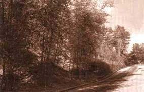
A stand of large bamboos can catch
debris and support the base of a slope
Construction steps: rooted culm cutting method
This is suitable for many large bamboos that have heavy branching. It can be used for choya/tama bans, dhanu bans and kalo bans. It requires a rooted culm cutting brought from a nursery (see Section 4.6 for details on this).
1 Keep the root ball wrapped in wet hessian until you are ready to plant it, so that it does not dry out.2 Remove all the loose debris from the site and carry out any other site preparation well in advance of the planting day.
3 Dig a sufficiently large hole and plant the cutting in it.
4 Carefully backfill the hole, making sure that you do not damage buds at the base of the cutting. Firm the soil.
5 Place a layer of mulch over the disturbed soil and the surrounding area.
6 Form a depression around the roots to act as a water collection area;
7 Water thoroughly.
Maintenance
This normally involves:
Protection (check on Kartik 1);
Watering in the first year (check weekly in Chaitra, Baisakh and Jestha);
Mulching in the first two years (check on Mangsir 1).
Main functions
Large bamboos support the base of a slope by establishing a very strong line of plants. With their multiple stems, they catch debris moving down the slope.
Main limitations
Bamboos take about five years to contribute significantly to slope strengthening. Protection is required in the early years. This technique cannot be used in most in hot, dry sites, since bamboos generally require cool, moist sites. Bamboos planted in steep upper slope situations are prone to slumping some years (seven or more) after planting.
3.10 Brush layering
Function
Woody cuttings (or hardwood cuttings) are laid in lines across the slope, usually following the contour. These form a strong barrier, preventing the development of rills, and trap material moving down the slope. In the long term, a small terrace will develop. The main engineering functions are to catch debris, and to armour and reinforce the slope. In certain locations, brush layers can be angled to provide a drainage function.
SPECIES SUITABLE FOR BRUSH LAYERING
|
Local name |
Botanical name |
Altitude range |
Sites summary |
|
Assuro |
Adhatoda vasica |
Terai - 1000 m |
Varied |
|
Bainsh |
Salix tetrasperma |
Terai - 2700 m |
Moist |
|
Dabdabe |
Garuga pinnata |
Terai - 1300 m |
Varied and dry |
|
Kanda phul |
Lantana camara |
Terai - 1750 m |
Hot and dry |
|
Namdi phul |
Colquhounia coccinea |
1000 - 2000 m |
Varied |
|
Phaledo |
Erythrina species |
900 - 3000 m |
Varied |
|
Saruwa/ bihaya |
Ipomoea fistulosa |
Terai - 1500 m |
Varied; hot or wet |
|
Simali |
Vitex negundo |
Terai - 1750 m |
Hot and dry; varied |

Brush layering. Lay the first
layer of cuttings along the terrace, with a 50 mm interval between the cuttings
(see also step 4);
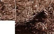
Brush layering. A second layer of
cuttings is placed on top (step 6);

Brush layering. Layers are
positioned at 1 to 2-metre intervals up the slope (step 8);
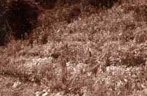
Brush layering. In the long term,
small terraces develop
Sites
This technique can be used on a wide range of sites up to about 45°. It is particularly effective on debris sites, fill slopes and high embankments. Avoid using the technique on materials that are poorly drained and are subject to high rates of small-scale slumping (see Section 3.13, Fascines, which may be more appropriate for poorly drained sites).
Materials
· Cuttings made from woody material that is 6 to 18 months old. They should be 20 to 40 mm in diameter and 450 to 600 mm long. When taking the cuttings, cut the top at right angles to the stem and the bottom at 45° to make it clear as to which way it should be inserted. If possible, take the cuttings the same day that they are to be planted.· Hessian and water to keep the cuttings moist until planting.
· Shovels and pick axes to make the trenches for planting.
· Line string.
· Tape measure (30 metres).
· For brush layering on gravel fill embankments, a supply of forest topsoil at the rate of 1 cu. m per 20 metres of layering.
Spacing
Spacing between brush layers depends on the steepness of the slope. The following spaces should be used.
|
Slope less than 30° |
2 m interval; |
|
Slope 30 to 45° |
1 m interval. |
Within the brush layers, cuttings should be at 50 mm centres, in the double layer described above. A wider gap than this is acceptable on gentle slopes, but on steep slopes this spacing is required to give adequate protection.
Construction steps
1 Using string, mark the lines to be planted, starting 500 mm from the base of the slope.2 Always install brush layers from the bottom of the slope, and work upwards.
3 Form a small terrace, with a 20 percent fall back into the slope. The terrace should be 400 mm wide. If you are brush layering a gravel-filled road embankment you should lay a 50 mm thick layer of soil along this terrace to improve rooting conditions.
4 Lay the first layer of cuttings along the terrace, with a 50 mm interval between the cuttings. Leave at least one bud and up to one-third of the cuttings sticking beyond the terrace edge and the rest inside. The branch growing tips should point towards the outside of the terrace.
5 Lay a 20 mm-thick layer of soil in between the cuttings to provide a loose cushion.
6 Lay a second layer of cuttings on top of this, staggered with the first layer. On a gravel-filled embankment slope lay an 80 mm layer of soil over the cuttings before you do any backfilling.
7 Partly backfill the terrace with the excavated materials. This should not be more than 50 mm thick.
8 Mark a line 1 metre above the first brush layer and set the string for the next layer.
9 Follow steps 3 to 7. As the next terrace is cut, always fill the lower bench with the material excavated from above and compact it reasonably well by gentle foot pressure.
Good site supervision is essential to ensure that lines run along the contours and do not concentrate runoff; also to make sure that cuttings are not allowed to dry in the sun. Well-buried cuttings have a higher survival rate.
Maintenance
Since the spacing of plants recommended here is very dense, there is unlikely to be a need for replacing failures, but some thinning of the trees or shrubs may be required after a few years. The main maintenance checks should be as follows.
Protection (check on Kartik 1);
Weeding (check on Shrawan 1, Bhadra 1 and Aswin 1);
Thinning (check on Kartik 1, starting three years after site works).
Main functions
Brush layering armours and reinforces the slope; it catches debris; and, if angled, it helps to drain the slope. Brush layers provide a very strong and low-cost barrier, especially on debris slopes, however loose.
Main limitations
The main limitation is that construction gives rise to a considerable level of disturbance to the slope.
3.11 Palisades
Function
Woody (or hardwood) cuttings are planted in lines across the slope, usually following the contour. These form a strong barrier and trap material moving down the slope. In the long term, a small terrace will develop. The main engineering functions are to catch debris, and to armour and reinforce the slope. In certain locations, palisades can be angled to give a drainage function.
Sites
This technique can be used on a wide range of sites up to about 60°. It is particularly effective on steep landslide debris slopes. Materials that are poorly drained and are subject to high rates of small-scale slumping should be avoided (see Section 3.13, Fascines, which may be more appropriate for poorly drained sites of up to 45°).
Materials
· Cuttings made from woody material that is 6 to 18 months old. They should be 20 to 40 mm in diameter and 300 to 500 mm long. Cut the tops at right angles to the stems and cut the bottom at 45°; it is then clear as to which way each cutting should be inserted. If possible, take the cuttings the same day that they are to be planted.· Hessian and water to keep the cuttings moist until planting.
· Pointed planting bars or crowbars to make the holes for planting.

A completed palisade
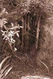
A simali palisade excavated after
one growing season to show the development of roots
Spacing
Spacing between palisades depends on the steepness of the slope. The following spaces should be used.
|
Slope less than 30° |
2 m interval; |
|
Slope 30 to 60° |
1 m intervals. |
Within the palisade lines, cuttings should be at centres of between 30 and 50 mm. A wider gap than this is acceptable on gentle slopes, but on steep slopes this spacing is required to give adequate protection.
SPECIES SUITABLE FOR PALISADES
|
Local name |
Botanical name |
Altitude range |
Sites summary |
|
Assuro |
Adhatoda vasica |
Terai - 1000 m |
Varied |
|
Bainsh |
Salix tetrasperma |
Terai - 2700 m |
Moist |
|
Dabdabe |
Garuga pinnata |
Terai - 1300 m |
Varied and dry; |
|
Kanda phul |
Lantana camara |
Terai - 1750 m |
Hot and dry |
|
Namdi phul |
Colquhounia coccinea |
1000 - 2000 m |
Varied |
|
Phaledo |
Erythrina species |
900 - 3000 m |
Varied |
|
Saruwa bihaya |
Ipomoea fistulosa |
Terai - 1500 m |
Varied; hot or wet |
|
Simali |
Vitex negundo |
Terai - 1750 m |
Hot and dry, varied |
Construction steps
1 Trim and clean the site well in advance of the planting operation. Remove irregularities and loose debris.2 With string, mark out the lines to be planted.
3 Always start at the top of the slope and work downwards.
4 Using a pointed bar, make a hole in the slope that is bigger than the cutting and deep enough to take at least two-thirds of its length.
5 Carefully place the cutting in the hole, so that at least two-thirds is buried. Firm the soil around it, taking care not to damage the bark. Ideally, only one node of the cutting or about the top 100 mm should protrude from the soil. On steep, unstable sites, however, a greater protrusion helps to raise the delicate new shoots above the zone of moving debris, and to catch more debris.
Good site supervision is essential to ensure that lines run along the contours and do not concentrate runoff; also to make sure that cuttings are not allowed to dry in the sun. Cuttings buried completely have a higher success rate than those planted with the tops partially exposed. Under extreme conditions, cuttings can be hammered into the slope. However, this is likely to cause physical damage and reduce the chances of success.
Maintenance
Since the spacing of plants recommended here is very dense, there is unlikely to be a need for replacing failures, but some thinning of the trees or shrubs may be required after a few years. The main maintenance checks should be as follows.
Protection (check on Kartik 1);
Weeding (check on Shrawan 1, Bhadra 1 and Aswin 1);
Thinning (check on Kartik 1, starting three years after site works).
Main functions
Palisades armour and reinforce the slope, catch debris and, if angled, provide drainage. They form a strong and low-cost barrier built with the minimum disturbance to the slope.
Main limitations
Palisades are not as strong as brush layering.
3.12 Live check dams
Function
Large woody (or hardwood) cuttings are planted across a gully, usually following the contour. These form a strong barrier and trap material moving downwards. In the longer term, a small step will develop in the floor of the gully. The main engineering functions are to catch debris, and to armour and reinforce the gully floor.
Sites
This technique can be used on a wide range of gully sites, on slopes of up to 45º. However, materials subject to high rates of small scale slumping should be avoided.
Materials
· Large cuttings (2 metres long and 20 to 50 mm in diameter) made from woody material that is 6 to 30 months old. Cut the tops at right angles to the stem and the bottom at 45°; it is then clear as to which way it should be inserted. If possible, take the cuttings on the same day that they are to be planted.· Truncheon cuttings 2 metres long and 30 to 80 mm in diameter, preferably of simali, dabdabe or phaledo.
· Hessian and water to keep the cuttings moist until planting.
· Pointed planting bars or crowbars to make the holes for planting.
Spacing
Spacing between check dams depends on the steepness of the gully slope and the profile of the gully floor. Live check dams should normally be at intervals of between 3 and 5 metres. Within the check dams, cuttings should be about 30 to 50 mm apart. A wider gap than this is acceptable on gentle slopes, but on steep slopes this spacing is required to give adequate protection. If a double, offset line is planted, it will give a much stronger check dam.

Backfill around the check dam and
compact the soil with foot pressure
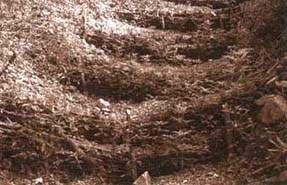
Live check dams form a strong
barrier on a wide range of gully sites, on slopes up to 45°
Construction steps
1 Choose a location for the live check dam so that the maximum effect can be achieved in terms of gully stabilisation.2 Make a hole deep and big enough to insert vertical hardwood cuttings of the largest size available (truncheon cuttings up to 2 metres in length of species such as dabdabe and phaledo are best). Use a crowbar if necessary to extend the hole.
3 Insert the vertical cuttings by carefully pushing them into the hole and firming the soil around them. Try not to damage the bark. They should protrude about 300 mm above the ground surface.
4 Place fascines or long hardwood cuttings on the uphill side of the vertical stakes.
5 Key these horizontal members into the wall of the gully.
6 Backfill around the check dam and compact the soil with foot pressure.
Maintenance
Since the spacing of plants recommended here is very dense, there is unlikely to be a need for replacing failures, but some thinning of the trees or shrubs may be required after a few years. The main maintenance checks should be as follows.
Protection (check on Kartik 1);
Weeding (check on Shrawan 1, Bhadra 1 and Aswin 1);
Thinning (check on Kartik 1, starting three years after site works).
SPECIES SUITABLE FOR LIVE CHECK DAMS
|
Local name |
Botanical name |
Altitude range |
Sites summary |
|
Horizontal cuttings |
| | |
|
Assuro |
Adhatoda vasica |
Terai - 1000 m |
Varied |
|
Bainsh |
Salix tetrasperma |
Terai - 2700 m |
Moist |
|
Kanda phul |
Lantana camara |
Terai - 1750 m |
Hot and dry |
|
Namdi phul |
Colquhounia coccinea |
1000 - 2000 m |
Varied |
|
Saruwa bihaya |
Ipomoea fistulosa |
Terai - 1500 m |
Varied; hot or wet |
|
Simali |
Vitex negundo |
Terai - 1750 m |
Hot and dry; varied |
|
Main vertical support member cuttings | |
| |
|
Dabdabe |
Garuga pinnata |
Terai - 1300 m |
Varied and dry |
|
Phaledo |
Erythrina species |
900 - 3000 m |
Varied |
The cuttings to provide vertical support should be of the biggest and strongest materials, In the form of truncheon cuttings (2 metres long and 30 to 80 mm in diameter). Dabdabe and phaledo are excellent for this. Other possible species are chuletro (Brassaiopsis hainla), kavro (Ficus lacor) and gliricidia (Gliricidia sepium).
Components of a live check
dam
Main functions
Live check dams catch debris and to a lesser extent, also armour and reinforce gully floors. They are an effective low-cost structure in smaller gullies, or can be used in between masonry check dams. Their flexibility and the relative lack of site disturbance during construction make them very suitable for use on weak materials, where civil engineering can easily be scoured around.
Main limitations
Large and very active gullies require stronger measures than can be provided by vegetation alone.
3.13 Fascines
Function
The word 'fascine' means a bundle of sticks. In this technique, bundles of live branches are laid in shallow trenches. After burial in the trenches, they put out roots and shoots, forming a strong line of vegetation. It is sometimes called live contour wattling. The main engineering functions are to catch debris, and to armour and reinforce the slope. In certain locations, fascines can be angled to provide drainage. Where time is at a premium, brush layers may be more appropriate as these are quicker to establish than fascines (see Section 3.10, Brush layering).
SPECIES SUITABLE FOR FASCINES
|
Local name |
Botanical name |
Altitude range |
Sites summary |
|
Assuro |
Adhatoda vasica |
Terai - 1000 m |
Varied |
|
Bainsh |
Salix tetrasperma |
Terai - 2700 m |
Moist |
|
Dabdabe |
Garuga pinnata |
Terai - 1300 m |
Varied and dry |
|
Kanda phul |
Lantana camara |
Terai - 1750 m |
Hot and dry |
|
Namdi phul |
Colquhounia coccinea |
1000 - 2000 m |
Varied |
|
Phaledo |
Erythrina species |
900 - 3000 m |
Varied |
|
Saruwa/ bihaya |
Ipomoea fistulosa |
Terai - 1500 m |
Varied; hot or wet |
|
Simali |
Vitex negundo |
Terai - 1750 m |
Hot and dry; varied |

Fascines are effective on
consolidated debris. They put out roots and shoots which develop into a strong
line of vegetation, catching falling debris as well as armouring and reinforcing
the slope

Fascines are effective on
consolidated debris. They put out roots and shoots which develop into a strong
line of vegetation, catching falling debris as well as armouring and reinforcing
the slope
Sites
Fascines are best used on consolidated debris or soft cut slopes. If the material is too hard, growth will be unacceptably slow. The maximum slope is about 45°. On well-drained materials, contour fascines are used; on poorly drained materials, a herringbone pattern (¬¬¬¬¬) of fascines is used to improve drainage.
Materials
· Woody cuttings of suitable species, at least one metre long and 20 to 40 mm diameter;
· Hessian and water to keep the cuttings moist until planting;
· Tools to dig trenches;
· (Optional) Jute or coir string or wire to bind the fascine as it is laid.
Spacing
Spacing between fascines depends on the steepness of the slope.
|
Less than 30° |
4 m interval; |
|
30 to 45° |
2 m interval. |
Within the fascines, there should be at least four but no more than eight cuttings.
Construction steps
1 Prepare the site well in advance of planting. Clear all loose material and protrusions and firmly infill depressions.2 Mark on the slope the lines where fascines are to be installed. Supervise workers carefully to ensure that the lines follow the contour or desired angle precisely.
3 Always construct fascines from the bottom of the slope, and work upwards.
4 Dig about five metres of trench at a time, carrying out Step 5 at the same time. This ensures that the soil in the trench is exposed only for a short period, thereby minimising the loss of residual soil moisture. The trench should be about 100 mm deep and 200 mm wide.
5 Lay the cuttings together, filling the trench and with their ends overlapping so that they form a single cable right across the slope. Four cuttings per bundle is normal, but use eight per bundle if there is a lot of material available or if the site is very critical.
6 The fascines can be bound as they are installed by first laying strings across the trench and then tying it when the cuttings are in place. This helps to keep the cuttings together during backfilling but is not essential.
7 Backfill the trench as soon as possible, lightly covering the cuttings, and tamp the soil down firmly around it.
8 If the slope angle is more than 25°, you should peg the fascine. This can be done by placing a large cutting at right angles into the slope immediately below the fascine. Use one peg per 500-mm run of fascines.
Maintenance
Since the spacing of plants resulting from fascines is very dense, there is unlikely to be a need for replacing failures, but some thinning of the shrubs may be required after a few years. The main maintenance checks should be as follows.
Protection (check on Kartik 1);
Weeding (check on Shrawan 1, Bhadra 1 and Aswin 1);
Thinning (check on Kartik 1, starting three years after site works).
Main functions
Fascines armour and reinforce the slope, catch debris and, if angled, provide drainage. They form a very strong and low-cost barrier, useful on a variety of sites.
Main limitations
Fascines do not form a physical barrier immediately as do brush layers, but require a period of growth to become effective. Construction causes disturbance to the slope.
3.14 Vegetated stone pitching
Function
Slopes are strengthened by a combination of dry stone walling or cobbling, and vegetation planted in the gaps between the stones. There are two distinct uses: (1) reinforced toe walls; and (2) protected gully beds. This technique provides a very strong form of armouring. Because it specifically uses vegetation to strengthen a simple civil engineering technique, it represents a stronger form of normal stone pitching (see Section 2.6).
Sites
Steep, low slope toe walls of up to 2 metres in height, and gully floors with a maximum slope of 45°.
Vegetated stone-pitched toe walls
These provide strong armouring at the base of a slope and prevent undermining. Where major support is needed, gabion or masonry toe walls may be required. Dry stone toe walls can only be used in limited applications. Walls using this technique should not be more than 2 metres high and should be laid back at an angle of about 60°.
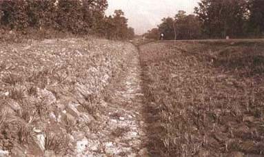
Cobbling with vegetation planted
between the stones provides strong armouring
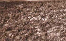
Cobbling with vegetation planted
between the stones provides strong armouring
Vegetated stone-pitched gully floors
Gully beds are cobbled to prevent downcutting, and then plants are established between the cobbles to stop them being pulled out by running water.
Materials
· Stones for construction.
· Hardwood cuttings or seeds of suitable shrubs (but not of large trees) for walls.
· Grass slips for gully floors.
Spacing
Plants should be established at 250 mm centres initially, on a random pattern.
Construction steps
Walls
1 Construct the wall normally, but make sure that there is plenty of soil in the backfill mixture;
2 once the wall is ready, wait until the monsoon rains are imminent. Then place the cuttings or seeds carefully between the stones, taking care not to damage the bark or seed coat.
Gullies
1 Clean the gully floor completely of all debris and excavate as necessary until a firm base is exposed;2 lay the stones carefully together, always keeping the flattest sides on the surface. Reduce gaps to a minimum and pack all voids with soil. The stone pitching should have a U-shaped cross-section to prevent scour at the sides;
3 once the monsoon rains have started, plant grass slips between the stones. Ideally, smaller grasses should be planted in the main channel, with larger grasses along the sides.
Maintenance
Since the spacing of plants in vegetated stone pitching is very dense, there is unlikely to be a need for replacing failures, but some thinning of shrubs may be required after a few years. The main maintenance checks should be as follows.
Protection (check on Kartik 1);
Weeding in the first few years (check on Shrawan 1, Bhadra 1 and Aswin 1);
Thinning (check on Kartik 1, starting three years after site works).
Main functions
Vegetated stone pitching provides a very strong form of armouring. This is particularly useful for gully floors carrying large flood discharges.
Main limitations
The main limitation is that over a large area it becomes costly; although relative to many toe walls or other forms of gully control, this may not in fact be limiting.
3.15 Jute netting (standard mesh)
Function
A locally made geotextile of woven jute netting is placed on the slope. Standard mesh jute netting (mesh size about 40 × 40 mm) has four main functions:
· Protection of the surface, armouring against erosion and catching small debris;· Allowing seeds to hold and germinate;
· Improvement of the microclimate on the slope surface by holding moisture and increasing infiltration;
· As it decays, it acts as a mulch for the vegetation established.
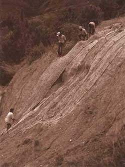
Jute netting is a temporary
measure, designed to enhance the establishment of vegetation
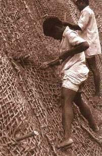
Ensure that the jute netting is
loose enough to be held against the surface over the whole slope.
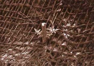
Live pegs will grow to add more
strength to the slope
Any use of jute netting is a temporary measure designed to enhance vegetation establishment. It does not protect a surface in itself for more than one or two seasons of monsoon rains.
Sites
Standard netting is used on steep, hard slopes where the existing conditions are too harsh for vegetation to establish itself without assistance. Slope angles of 45 to 60° are normal. It is best on well-drained materials that are too hard for vegetation to grow in unaided, or on slopes exposed to hot sun and where extreme drought would otherwise be a problem. It should not be used on soft or poorly drained materials. It should never be used on materials with a high rate of shallow slumping. Drainage is so important in sites treated with jute netting that slopes less than 45° should not normally be covered. This excludes all debris materials.
Materials
· Woven jute netting.· Hardwood cuttings from shrubs or trees, 20 to 50 mm in diameter and 300 to 400 mm long, or other pegs, such as split bamboos.
· Tools for cutting wood and jute; an iron bar for making holes, and a wooden mallet.
Standard jute netting rolls are normally 10.0 to 11.5 metres long by 1.0 to 1.2 metres wide. The yarn is of 5 to 8 mm diameter. Across the net there should be an average of 27 warp ends (length-ways threads) per metre; along the length of the net, there should be 20 to 24 weft strands (cross threads) per metre. The average mesh size should be 40 mm square holes. The weight should be 1.0 to 1.2 kg per square metre. These specifications are higher than those used in the Indian road sector (where 0.5 and 0.75 kg/sq. m are recommended). Experience has shown that the heavier grade material hangs better on the slope, catches more material, retains more moisture and remains effective for longer.
The life of jute netting can be extended by soaking in a bath of bitumen diluted with kerosene. However, this has the effect of reducing the water retention capacity of the material, which is a desirable attribute on many sites.
Spacing
Completely cover the affected area with netting, anchoring pegs spaced at 500 to 1000 mm centres.
Construction steps (standard netting)
1 Trim the site to an even slope, ensuring that there are no small protrusions or depressions that will interfere with the netting.2 Starting at one end of site, peg the end of one roll of netting 300 mm above the slope to be covered.
3 Slowly unroll the netting down the slope.
4 Allowing some slack in the netting, begin to peg it from the bottom of the slope. Hammer hardwood cuttings or pegs through it at intervals of 500 to 1000 mm, leaving the cuttings protruding about 80 mm.
5 Repeat the process, making sure that the vertical edges of the net meet, until the whole slope is covered in netting.
6 Place a series of pegs down each side of the net so that there is no gap between the strips.
7 Adjust the netting in order to reduce the tension and let it hug the surface closely. If it remains tight it will not lie right against the slope surface.
8 Add further pegs as necessary to ensure complete contact with the surface.
9 Trim the netting strips to the length required.
10 As soon as the monsoon rains permit, plant grass slips randomly through the netting over the entire area (see Section 3.4).
Integration with bio-engineering
Standard mesh jute netting should only be used in conjunction with bio-engineering techniques as follows:
· Through the netting: plant grass slips in a random pattern, at an average spacing of about 100 mm centres, according to site characteristics and as determined by the instructions in Section 3.4.· If a deeper reinforcing is required, the surface can be seeded with shrubs or small trees (direct seeding is best, but broadcasting is also possible), using species appropriate to the site and following the techniques described in Section 3.8.
It is important to ensure that the netted area becomes protected with vegetation during the first two planting seasons, because it has to take over the role of surface protection from the jute in that time.
Maintenance
The jute netting itself is not normally maintained, but simply allowed to rot away. Maintenance is carried out only for the bio-engineering measures.
Main advantages
A very effective aid to the establishment of a permanent grass cover on hard, dry materials on steep cut slopes.
Main limitations
Since jute netting forms a mulch, it raises the moisture content of the soil: if the material has poor internal drainage, this can lead to liquefaction following intense rainfall.
3.16 Jute netting (wide mesh)
Function
A locally made geotextile of woven jute netting is placed on the slope. Wide mesh jute netting (mesh size about 150 × 450 mm) is used to hold mulch on slopes that have been seeded.
Any use of jute netting is a temporary measure designed to enhance vegetation establishment. It does not protect a surface in itself.
Sites
Wide-mesh netting is normally used on any site where plant seeds have been covered in mulch, where the slope angle is between 30° and 45º. Sites less than 30° do not normally need netting to hold the mulch in place.
Materials
· Woven jute netting.· Hardwood cuttings from shrubs or trees, 20 to 50 mm in diameter and 300 to 400 mm long, or other pegs.
· Tools for cutting wood and jute; an iron bar for making holes, and a wooden mallet.
Rolls of wide-mesh jute netting are usually 10.0 to 11.5 metres long by 1.0 to 1.5 metres wide. The yarn is of 3 to 5 mm diameter. Across the net there should be an average of seven warp ends (length-ways threads) per metre; along the length of the net, there should be an average of three weft strands (cross threads) per metre. The average mesh size should be 150 × 450 mm rectangular holes. The weight should be 0.2 kg ±10% per square metre.
Spacing
Mulch (placed over seeds) is covered with netting. Anchoring pegs are normally placed at 500-mm centres.
Construction steps (wide mesh netting)
1 Place the netting only on to sites which have been seeded and covered in mulch: for details of these, refer to grass seeding (Section 3.5) and mulching (Section 3.17).2 Open the net to its full length and place it carefully on the slope.
3 Allowing some slack in the netting, begin to peg it from the bottom of the slope. Hammer hardwood cuttings or pegs through it at intervals of 500 mm, leaving the cuttings protruding about 80 mm.
4 Repeat the process, making sure that the vertical edges of the net meet, until the whole slope is covered in netting.
5 Place a series of pegs down each side of the join between strips and bind the strips of net together, so that the jute is held together as a continuous net.
6 Adjust the netting to ensure that it holds the mulch firmly on to the slope surface throughout the site.
7 Add further pegs as necessary to ensure complete contact with the surface.
8 Trim the netting strips to the length required.
Integration with bio-engineering
Wide mesh jute netting should only be used in conjunction with bio-engineering techniques as follows:
· Before the netting is applied, the slope is seeded with grass (see Section 3.5) and covered in mulch (see Section 3.17).· If a deeper reinforcing is required, the surface can be seeded with shrubs or small trees (direct seeding is best, but broadcasting is also possible if done before the mulch is applied), using species appropriate to the site and following the techniques described in Section 3.8.
Maintenance
The jute netting itself is not normally maintained, but simply allowed to rot away. Maintenance is therefore that of the vegetation, and the relevant part of Section 5 should be consulted for details.
Main advantages
A useful way of ensuring that mulch stays in position on a slope, while the seeds underneath germinate and establish a complete vegetation cover.
Main limitations
Like the mulch underneath, the jute netting is only a very temporary aid to vegetation establishment. Mulch cannot normally be held on slopes steeper than 45°.
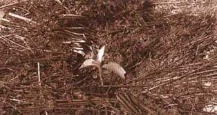
Mulching helps to keep the soil
cool and moist close to young
seedlings
3.17 Mulching
Function
Mulch is used only as a temporary measure to aid the establishment or growth of vegetation. Alone it will not protect a slope or establish a vegetation cover. There are two main ways of applying mulch: either it is placed around individual plants or it is applied over a whole slope.
In the first, it is to help keep the soil cool and moist, to enhance the growth and early establishment of shrub and tree seedlings, and particularly of large bamboos.
Where mulch is to treat the entire site, chopped plant material or brushwood is laid across the slope to form a surface cover. This is an extremely temporary measure useful only to help other plants establish. It is normally used to aid the establishment of grass seed, and therefore is a temporary form of surface armouring.
Sites
Any site suitable for grass seeding. This is almost any bare site with slopes up to 45°; mostly on well-drained materials, where increased infiltration does not give rise to problems. Also anywhere that large bamboos, or shrub or tree seedlings, have been planted.
Materials
· Cut stems and leaves of any plants. It is important not to use plant parts carrying seeds, as this will lead to a big weeding problem. Annual herbs such as ban mara (Eupatorium adenophorum) and tite pate (Artemisia vulgaris) are best if they are allowed to wilt before use. This is the only use of these plant species in bio-engineering.· On slopes greater than 30°, wide mesh jute netting (150 mm × 500 mm mesh size) is needed to hold mulch on to the surface (see Section 3.16).
Spacing
A complete cover of mulch to the depth described in the construction steps.
Construction steps
1 Collected material should be chopped to a maximum size of 150 mm. It can be stored until required if necessary.2 When mulching grass seeded areas, the mulch is evenly spread over the surface to give a cover of 50-mm thickness.
3 When mulching individual seedlings, the mulch is spread around the plant being treated in a layer between 50 and 100 mm thick. A circle of radius 150 mm should be left by the plant itself. Outside this, the mulch should form a circle of about 750 mm radius.
Integration with bio-engineering
Bio-engineering techniques should be used in connection with mulching as follows.
· Large areas: before the mulch is applied, the slope is seeded with grass (see Section 3.5); if the slope is greater than 30°, then the mulch should in turn be covered by wide mesh jute netting (see Section 3.16).· Where large bamboos have been planted, mulch is always applied around the new plant during the first two years.
· If the mulch is being used around other existing plants, then it is normally applied to aid the growth of planted shrubs or trees by keeping the soil cooler and more moist at the hot, dry time of the year.
Maintenance
This is a temporary technique, requiring no maintenance. Future maintenance is for the bio-engineering technique for which the mulch is an aid.
Main advantages
A cheap aid to the establishment of different kinds of vegetation, particularly important on hot and dry slopes, and where lack of soil moisture can limit growth.
Main limitations
Mulch is only very temporary in nature. Freshly cut ban mara and tite pate used in the monsoon may root and start to grow. It must be allowed to wilt in the sun before being applied to the site. Mulch carrying seeds can cause a massive problem from weeds.
3.18 Vegetated gabions
Function
Gabion walls are strengthened by trees growing on them. There are two distinct types: (1) normal stone gabions; and (2) earth-filled gabions. This technique provides a form of slope support.
Sites
Any slope where gabion walls are suitable for slope retention. Stone gabions require damp sites for trees to establish on them.
Vegetated stone gabions
These tend to come about naturally where trees have seeded existing gabion walls, although they could be seeded artificially. There is no distortion of the gabion boxes. The benefit is that the trees will provide flexible binding to the structure once the wire has corroded.
Vegetated earth-filled gabions
These have been tried in some locations as a lower-cost alternative to stone gabions. A fill of in situ earth is placed behind a single layer of dry stone within the gabion basket (the stone layer prevents the washing out of the earth fill). Tree seedlings are planted on the gabion.
Materials
· Stones, wire and tools for gabion construction. In earth-filled gabions, the material from the excavation is used as a fill.· For stone gabions, seeds of suitable trees: utis (Alnus nepalensis) and dar (Boehmeria rugulosa) colonise existing walls most often. Alternatively, if holes can be made right through the gabion wall, long hardwood cuttings can be used of species such as dabdabe (Garuga pinnata) or phaledo (Erythrina species).
· For earth-filled gabions, polypot seedlings of tree species appropriate to the site.
Spacing
Plants should be established at 500 mm centres initially, on a random pattern.
Construction steps
1 Construct the gabion normally, depending on the fill type.2 For stone gabions, sow the seeds directly into the gaps between the stones. A rate of 25 seeds per cu. m of gabions allows for the high rate of failure, which should be expected.
3 If hardwood cuttings are to be used, a hole must be made right through the gabion into the original ground below. This is normally practical only for gabion mattresses or revetments of 1-metre thickness.
4 For earth-filled gabions, plant four polypot tree seedlings per cu. m of gabion at an equal spacing in the top panel of each box.
Maintenance
Since the spacing of plants in vegetated gabions is very dense, there is unlikely to be a need for replacing failures, but some thinning of trees may be required after a few years. The main maintenance checks should be as follows:
Protection (check on Kartik 1);
Weeding in the first few years (check on Shrawan 1, Bhadra 1 and Aswin 1);
Thinning (check on Kartik 1, starting three years after site works).
Main functions
Vegetated gabions may offer a lower cost option for supporting certain slope types.
Main limitations
For stone-filled gabions, trees are unlikely to contribute much to the strength of the structure until the wire has corroded seriously. The stability of a gabion wall with serious corrosion problems, with or without trees, is not well researched in Nepal, and remains uncertain at present. Numerous observations demonstrate that tree roots do not distort gabion structures, as is sometimes claimed.
The use of vegetated earth-filled gabions may well have great potential in Nepal. Experiments have been limited in scope and the results have consequently not been conclusive. At the time of writing this manual, the Geo-Environmental Unit of the Department of Roads had not recommended them for use on the strategic road network; but nor had it ruled them out as a future possibility.
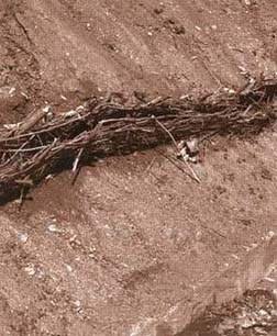
Live wattle fences can be
effective at catching falling debris on gentle
slopes
3.19 Live wattle fences
Function
Fences made out of live cuttings are placed across the slope. Debris moving down the slope is trapped behind them. This is a relatively poor technique used to catch material on gentle slopes.
Sites
Slopes up to a maximum of 30°.
Materials
The following will be required:
· Hardwood cuttings, as for fascines, at least 1 metre long and 20 to 40 mm in diameter.
· Hessian and water to keep the cuttings moist.
· Tools for digging grooves in the slope.
Spacing
Wattle fences should be placed about every 4 to 5 metres down the slope.
Construction steps
1 Prepare the site well in advance of planting. All loose material and protrusions should be cleared away, and depressions firmly infilled.2 Mark on the slope the lines where wattle fences are to be installed. Careful supervision will be required to ensure that the lines follow the contour precisely.
3 Place pegs at intervals of about 250 mm along the lines: this is done by placing large cuttings into the ground. Pegs should protrude about 300 mm.
4 Dig out a groove along the contour between the pegs: it should be at least 100 mm deep.
5 Place the cuttings with their lower ends in the groove, bending them down along the line of the fence. Weave them in and out between the pegs. Firm the soil back into the groove.
6 The end result should have the cuttings almost horizontally above each other, but with the ends firmly planted in the soil.
Maintenance
Because the spacing of plants in wattle fences is very dense, there is unlikely to be a need for replacing failures, but some thinning of shrubs may be required after a few years. The main maintenance checks should be as follows:
Protection (check on Kartik 1);
Weeding in the first few years (check on Shrawan 1, Bhadra 1 and Aswin 1);
Thinning (check on Kartik 1, starting three years after site works).
Main functions
Live wattle fences catch debris moving down the slope, and have limited functions of armouring and reinforcement.
Main limitations
Often the structure is too weak to support the volume of debris that is caught. They have not been found to be as effective as techniques such as brush layering and fascines; or, on more critical slopes, as reliable as wire bolster cylinders.
3.20 Hydro-seeding
Function
'Hydro-seeding' covers a range of possible options, which use high pressure pumps to spray a mixture of seed and mulch, and sometimes other materials, directly on to a slope. These techniques provide a random cover of vegetation and do not have the structural benefits of manual bio-engineering systems. The main functions are to armour and reinforce the slope.
Sites
Hydro-seeding is reputed to be capable of use on almost any site. However, pumps and their hoses tend to limit reach to a maximum of 100 metres or less from the nearest road point. This technique should not be used on poorly drained materials, where there is any risk of slumping or shallow mass movement.
Experience in Nepal
At the time of writing this handbook, there had never been any widespread use of hydro-seeding in Nepal. The Department of Roads, through several donor-assisted projects, had conducted experiments on a number of different technical systems. There appears to be scope for these techniques on well-funded road construction projects, but a number of limitations affect its routine use in maintenance activities. These limitations are chiefly as follows: (1) high cost, complex machinery is required to spray the mixtures; (2) a large number of inputs (such as seed, mulch, and fertiliser) are required; (3) a number of special skills are required for the team implementing the work; (4) the unit cost is extremely high for small areas, but diminishes with increased scale.

Manual methods of bio-engineering
are cheaper and easier to implement than mechanical techniques such as
hydro-seeding

Manual methods of bio-engineering
are cheaper and easier to implement than mechanical techniques such as
hydro-seeding
For routine works, the experience of the Department of Roads, and of most projects, is that the manual methods of bio-engineering described in this handbook are cheaper and more straightforward to implement. They also allow very precise treatment of slope surfaces.
Materials
· High pressure solids pump, with mixing tanks, agitators, hoses and spray nozzles.· A lorry with a mounted crane to carry the pump, tanks and other equipment.
· A water tanker.
· For steep slopes greater than 15 metres above or below the road, scaffolding is required.
· A mix (between 1 and 30 litres per sq. m) of seeds (usually grasses and shrubs), fertiliser, mulch, soil improver, binding agent and water. Some methods also add a mixture of forest topsoil and clay loam to improve surface rooting conditions, bringing the mix to about 100 litres per sq. m (i.e. 0.1 cu. m/sq. m).
Construction steps
1 Prepare the site well in advance of planting. Remove all debris and either remove or fill in surface irregularities so that there is nowhere for erosion to start. If the site is on backfill material, it should be thoroughly compacted, preferably when wet.2 Collect together the various materials needed for the operation. It is normal to have a training session with the hydro-seeding team in a suitable off-site location.
3 Mix the ingredients together in the tank and spray them on to the site immediately. Delays cannot be allowed because of the need to keep all parts of the mixture agitated in suspension, and because the binding agent will start to act.
4 The thickness of the surface cover depends on the technique being used and the nature of the sprayed mixture. A minimum of 5 to 20 mm is normal. Techniques adding a soil base are usually 50 to 100 mm thick, often requiring two sprayings.
Maintenance
Since the spacing of plants resulting from hydro-seeding is very dense, there is unlikely to be a need for replacing failures, but some thinning of the shrubs may be required after a few years. The main maintenance checks should be as follows:
Protection (check on Kartik 1);
Weeding (check on Shrawan 1, Bhadra 1 and Aswin 1);
Thinning (check on Kartik 1, starting three years after site works).
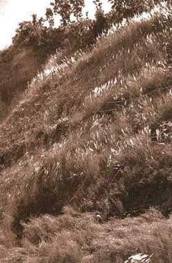
Hydro-seeding can yield
spectacular results for surface covering, but this example was estimated to cost
about thirty times more than the manual method
Main functions
Hydro-seeding is used in many countries to armour and reinforce slopes. The vegetation also has a limited catching effect. In appearance, the overall results often appear spectacular.
Main limitations
Hydro-seeding has none of the structural advantages of the planted grass lines, or techniques such as brush layering and fascines. It lacks the detailed treatment of site conditions offered by all the manually applied techniques. However, the greatest limitations lie in the relatively high cost, and its reliance on a wide range of complex inputs, of which the high-pressure pump is only one.
|
| ||||||||||||||||||||||||||||||||||||||||||||||||||||||||||||||||||
Roadside Bio-Engineering - Site Handbook (DFID, 1999, 160 p.)
Sector Four - Production of bio-engineering plants

Figure
This section gives the following information:
· where to establish a nursery (Section 4.1);
· the components, layout and materials of a nursery (Section 4.2);
· propagation of grasses (Section 4.3);
· propagation of shrubs and trees (Section 4.4);
· propagation of bamboos (Section 4.5);
· nursery management (Section 4.6);
· seed collection and storage (Section 4.7);
· assessing the quality of bio-engineering nurseries (Section 4.8)

Figure 4.1: Nursery activity
calendar: low-altitude nurseries For nurseries below about 1200 to 1500
metres above sea level

Figure 4.1: Nursery activity
calendar (continued): high-altitude nurseries For nurseries above about 1200
to 1500 metres above sea
level
4.1 Nursery establishment
What are nurseries for?
A nursery is a factory to supply plants, in this case, for a bio-engineering programme. A good nursery will supply:
· enough plants of the right species,
· in good, healthy condition,
· in the form required for planting;
· at the right time; and,
· at a reasonable cost.
Young plants are delicate organisms and their production is a skilled business. For this reason, nurseries require careful organisation and operation.
When are nurseries used?
Nurseries are a permanent feature. The production of plants is seasonal at lower altitudes (below about 1200 or 1500 metres, depending on the warmth of each individual nursery location) but continues throughout the year above this altitude. The calendars in Figures 4.1 show the variations.
Selecting a suitable site
Before choosing a site, carefully define the objectives of the nursery, including:
· the approximate number of plants of each type (i.e. grass, shrubs/trees and bamboos) to be produced each year;· the location of the planting sites that the nursery must supply;
· the availability of land belonging to the Department of Roads.
The choice of site is the single largest factor affecting the quality of plants. The nursery must be carefully prepared to receive seeds and cuttings. Therefore, you must choose the site at least six months before the first seed is to be sown.
Nurseries need to be on land owned by the Department of Roads (or leased for at least 10 years) and as close as possible to the sites they will serve. At the same time, however, the location must be technically suitable. You will rarely be able to get everything just right, so the final selection should be based on evaluating the relative advantages and disadvantages of three or more possible sites after you have thoroughly inspected them
The following are the main technical factors that must be satisfied when establishing a nursery.
Water supply
A reliable, adequate water supply is essential for all nurseries. A guaranteed supply is required at the following rates:
· 150 litres (0.15 cu. m) of water per day for every 10 sq. m of grass beds;
· 500 litres (0.5 cu. m) of water per day for every 10,000 polypot seedlings;
if watering is done with a watering can, and rather more for watering with hose pipes. Whatever the source of the water, check that it is available throughout the year; especially check the flow in the driest months: March, April and May (Chaitra to Jestha).
Figure 4.2: Calculating the nursery size
|
NURSERY COMPONENT |
CALCULATION BASIS |
AREA ALLOWED |
|
Office/Store/Chowkidar's hut |
Estimate |
Normally allow 15 sq. m |
|
Vehicle access and turning area |
Estimate |
Normally allow 50 to 100 sq. m |
|
Pathways to all parts of the nursery |
Estimate |
Normally allow 50 to 100 sq. m |
|
Working area |
Estimate |
Normally allow 25 sq. m |
|
Soil and sand stores |
Estimate |
Normally allow 20 sq. m |
|
Compost bays |
Standard size |
Normally allow 10 sq. m |
|
Water tank and accessories |
Standard size |
Normally allow 10 sq. m |
|
Drainage systems |
Estimate |
Normally allow 25 to 50 sq. m |
|
Grass beds: see Figure 4.4 |
100 cuttings per sq. M |
Depends on requirement: see below |
|
Seed beds | |
Normal requirement Normally allow 5 sq. m |
|
Standout beds for polypot seedlings |
128 polypots per sq. m |
Number of seedlings required × 1.25 ÷ 128 |
|
Beds for hardwood cuttings |
40 cuttings per sq. m |
Above 1500 m: number required × 2 ÷ 40 |
| | |
Below 1500 m: number required ÷ 40 |
|
Bamboo beds |
4 cuttings per sq. m |
Above 1500 m: number required × 3 ÷ 4 |
| | |
Below 1500 m: number required × 2 ÷ 4 |
|
Space between beds |
Estimate |
Total area of beds × 0.75 |
|
Space for terracing on slopes |
Estimate |
Total area of nursery × 0.5 |
General location
The site should be near to the road and as close as possible to the centre of the area to which plants will be supplied.
Physical features
Aspect is very important. North-facing slopes are cooler and more humid and are better for nurseries at lower elevations, whereas nurseries above 1200 metres are better on warmer southern slopes.
Drainage is important to avoid waterlogging of the beds. In the Terai, a slope of 2 - 3 percent is best if possible. In the hills, terracing is usually necessary.
Avoid areas threatened by landslides, flooding or strong winds, and at higher elevations avoid sites which are particularly liable to frost (e.g. small valley bottoms).
Availability of materials and labour
You should select a location with the best quality soil available. If possible, it should be an old forest soil, loamy and with a good content of organic matter, and on a well-drained site.
Additional soil will be required for the production of polypot seedlings. This should be a sandy loam forest topsoil; if the available soil is too heavy (i.e. contains too much clay), sand will also be required.
Easy access to stone for building the nursery wall and beds as well as other items, such as a water tank, a shed and a compost bin, is also an advantage. Otherwise stone or bricks have to be brought in.
A lot of labour is required for constructing the nursery and later on for tasks like transplanting grasses, carrying soil and filling pots. You should locate the nursery where it is possible to obtain labour without difficulty at most times of the year.
Calculating the appropriate size
The amount of space required for a nursery depends upon the number of plants to be produced, the time they will spend in the nursery and the density at which they will stand in the beds. The slope and the quality of the site will also influence the decision on how much space to allocate.
Before you start to calculate the area needed, list the various components of the nursery that you require and calculate the area required for each. Figure 4.2 summarises this.
Figure 4.2: Calculating the nursery size (continued): worked examples
|
NURSERY COMPONENT |
TERAI NURSERY** |
NURSERY AT 1400 METRES |
NURSERY AT 2000 METRES |
|
Fixed elements (Office/Store/ Chowkidar's hut, vehicle access, pathways, working area, soil and sand stores, compost bays, water tank and drainage) |
265 sq. m |
265 sq. m |
265 sq. m |
|
Grass beds |
290 |
633 |
633 |
|
Seed beds |
5 |
5 |
5 |
|
Standout beds for polypot seedlings |
98 |
98 |
195 |
|
Beds for hardwood cuttings |
25 |
25 |
25 |
|
Bamboo beds |
50 |
50 |
75 |
|
Sub-total: beds |
468 sq. m |
811 sq. m |
958 sq. m |
|
Space between beds |
351 |
608 |
718 |
|
Sub-total: all above components |
1,084 sq. m |
1,684 sq. m |
1,941 sq. m |
|
Space for terracing on slopes |
0 |
842 |
970 |
|
Total area required* |
1,084 sq. m |
2,526 sq. m |
2,912 sq. m |
*1 ropani = 0.052 hectare.**Assume that each nursery is expected to produce, per year 100,000 grass slips, of which 10,000 are amliso; 10,000 polypot shrub and tree seedlings; 1,000 rooted hardwood cuttings; and 100 rooted bamboo culm cuttings.

Figure

Figure 4.3: Typical low-altitude
nursery that has been well laid out
The main components of a nursery are as follows:
|
General: |
Compound wall or fence |
| |
Office/Chowkidar's hut |
| |
Vehicle access and turning area |
| |
Pathways to all parts of the nursery |
| |
Working area |
|
Storage: |
Nursery store |
| |
Soil and sand stores |
| |
Compost bays |
|
Water: |
Water tank and accessories |
| |
Drainage systems |
|
Beds: |
Grass beds |
| |
Seed beds |
| |
Standout beds for polypot seedlings |
| |
Bamboo beds |
| |
Shades for beds |
Other areas and corners for perennial grass and hardwood stock plants
How to estimate the requirement for grass beds
Grass slips are produced in nursery beds from cuttings made from either a portion of root and stem, or just stem. They are planted in nursery beds at a density of 100 per sq. m.
Bio-engineering nurseries have to produce more grass slips than any other plants. It is therefore important to estimate the quantity of grass slips required, and the nursery space they need, early on. This is done in two stages: determining the number of slips per planting drill, which depends on the type of grass; and then calculating the multiplication factor for the production of the grass.
Number of grass slips per planting drill
The planting drills described in the rate analysis norms, given in the Reference Manual, consist of different numbers of slips, depending on the type of grass, the nature of its rooting and the parts used for vegetative propagation. Rhizomatous grasses1, such as amliso, require only one slip per planting drill. Fibrous rooting grasses, such as babiyo, kans, khar and phurke, require two slips per drill. Grasses grown from single or double-node stem cuttings, such as dhonde, narkat and napier, require only one slip per planting drill.
1 Some grasses, especially bamboos, grow with a form of underground stem called a rhizome. Roots and shoots form from nodes on the rhizome.
Calculation of grass slip multiplication in the nursery
The nursery multiplication of grasses by slips produces a three to seven times increase in the number of plants each time the grass clumps are split out, depending on the species, altitude and time of planting in the nursery. At altitudes below 1200 metres, slips of grasses except amliso can be multiplied by seven times; amliso can usually only be multiplied by three times. At higher altitudes, usually above about 1200 metres, a three-times multiplication is usually only possible in one warm season. However, the timing of planting in the nursery bed also regulates the productivity. Figure 4.4 summarises all this information.
How to estimate the requirement for hardwood cutting beds
Hardwood cuttings can be propagated at the rate of 40 cuttings per square metre of bed. However, in nurseries above 1500 metres, you need to allow two complete bed areas. The reason for this is that above 1500 metres the cuttings often have to remain in the nursery for 16 months or more.
Figure 4.4: Calculation of grass slips numbers
|
NURSERY ALTITUDE |
PROPAGATION METHODS |
SPECIES |
CUTTINGS PLANTED IN NURSERY |
NUMBER TO PLANT |
|
Above 1800 m |
Rooted slip cuttings |
Amliso |
Previous August |
Final site number ÷ 3 |
| | |
Any other grasses |
Previous August |
Final site number × 2 ÷ 3 |
| |
Stem cuttings |
Dhonde, narkat |
Previous August |
Final site number × 0.25 |
|
1200 to 1800 m |
Rooted slip cuttings |
Amliso |
February/March |
Final site number ÷ 3 |
| | |
Any other grasses |
February/March |
Final site number × 2 ÷ 3 |
| |
Stem cuttings |
Dhonde, narkat |
February/March |
Final site number × 0.25 |
|
Terai to 1200 m |
Rooted slip cuttings |
Amliso |
February |
Final site number ÷ 3 |
| | |
Any other grasses |
February |
Final site number × 2 ÷ 7 |
| | |
|
April/May |
Final site number × 2 ÷ 3 |
| |
Stem cuttings |
Dhonde, narkat |
March |
Final site number × 0.25 |
Figure 4.5: Main construction features of nursery beds
|
BED TYPE |
GRASS BEDS |
SEED BEDS |
STAND OUT BEDS |
BAMBOO CUTTING BEDS |
|
Purpose |
Beds for grass seeds, grass slips, hardwood and stump cuttings of shrubs and trees |
Very finely prepared beds for germinating small shrub and tree seeds |
Frames in which to stand polypot seedlings |
Beds for the propagation of bamboo culm cuttings |
|
Bed size * |
1000 mm wide × 250 mm high |
1000 mm wide × 170 mm high |
1000 mm wide × 150 mm high |
1000 mm wide × 300 mm high |
|
Details of construction |
50 mm of washed gravel placed above the ground; then 50 mm of 1:1 mix of sieved soil and compost; and topped with 150 mm of 3:1 mix of sieved forest topsoil and washed sand |
50 mm of washed gravel placed above the ground; then 50 mm of unsieved forest soil; 50 mm of 1:3 mix of sieved forest soil and washed sand; and topped with 20 mm of washed, sieved and sterilised sand. |
50 mm drainage layer of gravel placed above compacted ground. A flat stone or brick surround |
Ground below the bed is dug to a depth of 300 mm. Bed is made with 100 mm of unsieved soil (lower) and 200 mm of sieved soil (upper). A bund 100 mm high is formed around the edge |
|
Shade type |
No shade; hessian sheet can be laid on the surface if required |
Complete top shade of thick thatch and polythene sheet |
Removable top shade of rolling bamboo slats, made from split culms |
Top shade of thick thatch; side shades of hessian sheet |
* Beds may be constructed to any length
How to estimate the requirement for bamboo beds
Bamboo culm cuttings can be propagated at the rate of four cuttings per square metre of bed. However, in nurseries below 1500 metres, you need to allow two complete bed areas, and in nurseries above 1500 metres, three complete bed areas. The reason for this is that below 1500 metres the cuttings remain in the nursery for 16 months and, above 1500 metres, for 28 months.
Layout and construction of the nursery
Nurseries are essentially a form of factory and need to be laid out with the production process in mind. Some aspects are usually pre-set. For example, the point of road access is usually fixed. The office/store/chowkidar's hut is normally placed near this gate. In the hills, the water tank has to be at the highest point of the nursery in order to allow gravity feed by hose pipe; in the Terai it should be located in the centre, as water is needed equally throughout the nursery (see Figure 4.3).
Other considerations are as follows.
· Place the soil and sand store beside the vehicle access and turning area.· Locate the working area beside the soil and sand store.
· Locate the seed beds close to the chowkidar's hut, since these require more attention.
· If it is a remote area, make the chowkidar's hut big enough for his family as well.
· Ensure easy access to all parts of the nursery. Do not put the beds too close together. Remember that when shades are erected, they will reduce the space between the beds.
· Make sure that the whole nursery is well drained. In particular, check that there is no risk of any of the plant beds being flooded.
· Use any remaining corners and rough areas for long-term production of grass and hardwood cuttings.
All construction must be done to a high standard, as per the norms and specifications. Nurseries are usually permanent fixtures, and therefore must be designed and built to last.
Figure 4.5 summarises the main features of nursery bed construction.
4.2 Components of a nursery
Nursery equipment
Main permanent equipment
The main equipment required is as follows.
|
Pate kuto |
Chuche kuto |
|
Hasiya |
Shovel |
|
Kodalo |
Kodali |
|
Chuppi |
Khukuri |
|
Dante |
Axe |
|
Hammer |
Doko |
|
Crowbar/khanti |
Watering can with roses |
|
Hose pipe |
Scissors/secateurs |
|
Tin trunks with |
Flit gun sprayer |
|
padlocks |
Leather or paper punch |
|
Soil and sand sieves |
First aid kit |
Tape measure
Plant carrying trays (metal or wood, ideally 400 × 2009 mm, with sides 100 to 200 mm high)
Seed trays (optional; make by cutting oil tins in half).
Tools and equipment must be kept in good working order. Replace defective items before they are needed, and keep blades sharp.
Expendable materials
The main expendable materials required are as follows:
|
Soil |
Sand | ||
|
Compost |
Seeds | ||
|
Grass slips |
Bamboo cuttings | ||
|
Hardwood cuttings |
Fungicide and insecticide | ||
|
Fertiliser |
Polypots: 4" × 7", 200 | ||
|
Heavy gauge |
|
gauge black | |
| |
polybags for |
|
polythene |
| |
storage |
polythene sheeting | |
|
Shade material |
String | ||
| |
(bamboo, |
Wire mesh | |
| |
thatch, hessian) |
Soap | |
|
Wire |
Waterproof marker pens | ||
|
Nails |
Registers: grass slip/ | ||
|
Seedbed labels |
|
hardwood cutting, | |
|
Pens/pencils |
|
seedling | |
Expendable materials need to be re-supplied each year and you should order them well in advance, normally by the end of Mangsir, after discussion with the naike.
Most of these materials are simple and easily obtainable. Some technical details about the more complex items are given below.
Soil
For polypot seedlings especially, you will need to bring in large quantities of sandy loam or loam forest topsoil. If only heavy soils such as clays are available, they will have to be mixed with sand.
|
SOIL TEXTURE TEST You can tell when the soil texture is right by trying to roll a little moist soil to pencil thickness between your fingers. If this is not possible, there is too much sand. If the roll can be bent in a semi-circle without breaking, there is too much clay. |
Certain species of trees have special requirements for micro-biological soil constituents. To satisfy these, you need to try to collect soil from under existing stands of the trees concerned. The species in this category are given below; of all of them, it is most important that soil for pine seedlings comes from under pine trees (the other species usually grow reasonably well without the relevant microbes).
Pines (salla) require special mycorrhizal soil1.The legume genera Acacia (e.g. khayer), Albizia (siris) and Dalbergia (sisau) require soil containing Rhizobium bacteria2.
The genus Alnus (utis) requires soil containing Frankia3.
1 Mycorrhizae are a living arrangement produced between special fungi and the roots of a plant, which increase the growth of the plant considerably. This is a form of symbiosis, where two organisms live together for mutual benefit. Soils from pine forests contain the necessary fungi to bring this about.2 Rhizobia are the nitrogen-fixing bacteria that form nodules on the roots of many leguminous species, including those listed here.
3 Frankia are actinomycetes that form a symbiotic relationship with the roots of certain species, and which also fix nitrogen.
The quantity of soil required is often under-estimated. A nursery with a target of 10,000 usable plants would fill 12,500 pots. For 100 × 175 mm (4" × 7" inch) pots, this would require 6.1 cu. m of potting mixture. For a 2:1:1 soil: sand: compost mixture you would need about 3.1 cu. m of soil and 1.6 cu. m of sand, which would weigh about 4.5 and 2.7 tonnes. If sieving was done in the nursery you need 15 percent more soil and 5 percent more sand.
Compost
Details of the making and use of compost are given in Section 4.6. Compost is used to enrich the soil in the nursery beds.
Seeds
Seed collection and storage is covered in Section 4.7.
Grass slips
The collection and propagation of grasses from slips are covered in Section 4.3.
Hardwood cuttings
The propagation of shrubs and trees from hardwood cuttings is covered in Section 4.4.
Bamboo cuttings
The propagation of bamboos in nurseries from single node culm cuttings is described in Section 4.5.
Registers
The use of nursery registers is described in Section 4.6. The register forms are given in Annex C.
Nursery staff
Each nursery normally requires a staff of one naike, one watchman and two labourers. During the peak nursery season of February to June (Magh to Ashad), the number of labourers may need to be increased to five.
The staff of bio-engineering nurseries should be drawn from rural areas, to ensure that they have a good understanding of how to handle delicate plants. Only naikes and specialist seed collectors are considered to be skilled workers. The abilities and roles of the various staff are given below.
Nursery naikes
Naikes (or nursery foremen) are each responsible for the operation of one nursery. They must understand all aspects of nursery work and be able to motivate labourers and keep them busy. Training is usually necessary, but this can either be done within the Division (perhaps by the Supervisor), by attachment to another Division with a well-established nursery, or with help from the Geo-Environmental Unit. Literacy (in Nepali) is required for record keeping. The Naike should work full time in his nursery and manage his team of labourers. Duties include:
1 Daily operation of the nursery and attendance to all matters concerned with keeping a clean and healthy environment for seedlings and plants to thrive in.2 Carrying out with due care all nursery operations.
3 Reporting to the local and senior road line supervisors any problems of plant health or growth.
4 In general, the provision of quality planting material for use in roadside planting.
5 Keeping records of all nursery stock.
In summary, nursery naikes should have the following attributes:
· good understanding of local plants;
· experience in nursery work;
· very active in the nursery at all times;
· knowledge of seed collection, treatment and storage;
· know how to motivate others.
Nursery watchmen
Anyone employed as a watchman has to be thoroughly trustworthy. He will be working alone all the time and has to be sufficiently motivated to work long hours in uncomfortable conditions. He should be in the nursery 12 hours a day or night, seven days a week. The best watchmen are usually the most reliable of the labour force and may be non-literate and poorly educated. In summary, nursery watchmen should have the following attributes:
· reliable and trustworthy;
· intelligent approach to work and show initiative;
· self motivated.
Labourers
Whenever possible, employ local farmers as labourers as they have a good understanding of plants. They should be from as close to the nursery or work site as possible. There is no need for literacy, but a good level of intelligence helps a lot. In summary, nursery labourers should have the following attributes:
· local farmers;
· good understanding of local plants;
· reliable.
Seed collectors
Seed collection requires skilled personnel who have been specifically trained for the job. There are three distinct elements: timing of seed collection and selection of good seed trees; ability to climb trees safely and pick the seeds; and knowledge of seed treatment and storage. People selected for this job should, therefore, be experienced, with a sound knowledge of local trees.
Some literacy is useful for reading training information and seed-collection calendars. In summary, seed collectors should have the following attributes:
· good understanding of local plants;
· knowledge of seed collection, treatment and storage;
· specially trained in tree climbing and seed collection.
In practice, each Division or project is unlikely to have specially trained seed collectors. Instead, labourers who are particularly good at this can be retained on the payroll to ensure that they are always available.
Tree climbing equipment can be partly purchased and partly made in the nursery. The Department of Forests sometimes gives training courses on making equipment.
The following questions can be used when interviewing people who are possible employees as nursery naikes, watchmen and labourers.
· Have they worked in the subject area before? For how long? Where?
· Have they ever done anything beyond the normal requirements of their job? What?
· How can you show a previous interest in or commitment to this job?
· What do they know about this job and why do they think they can do it?
· What tasks required in this job have they actually performed before?
· Have they ever worked in a team before? To do what?
· Have they ever organised others to work before?
· Have they ever had a bad accident or injured anyone? How?
· Do they live locally? Where exactly?
· How much land do they have? What do they grow on it? Do they have many private trees?
· Why did they leave their last job?
· How many days per month do they take off?
· Ask them to show you a khukuri or hasiya; if it is sharp and in good condition, the person should know how to look after their tools.
4.3 Propagation of grasses
This section explains how to produce grass plants in simple soil beds in a nursery.
Introduction: the methods of grass production
Perennial grasses usually form the main part of a bio-engineering scheme. Propagating these grasses vegetatively (i.e. from cuttings) is not difficult technically and various vegetative methods of propagation are highly successful. However, the reason for using a particular propagation method in the nursery is often related to the availability of material.
There are three methods for propagating grasses in bio-engineering, as described in Figure 4.6. Some grasses (e.g. dubo and kikiyu) can also be propagated from stolon cuttings1, but these are not normally used in bio-engineering. Seed is a cheap means of propagating grasses, but requires much longer growing in the nursery before the plants can be used on site.
1 A stolon is a stem that grows along the ground, producing at its nodes new plants with roots and upright stems.
Grasses from cuttings always grow much faster than those produced from seed. Also, they are tougher and do not go through such a delicate stage as seedlings.
Propagation of grasses from slip and rhizome cuttings
All of the bio-engineering grasses can be propagated by this method. It is by far the most widely used method of propagation in bio-engineering.

Grass clumps are split up and
trimmed.

Grass clumps are split up to make
slips.
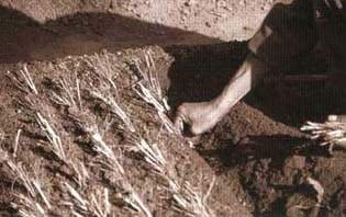
Slips are then planted in nursery
beds to multiply.
Take a clump of the grass, cut the shoots off about 100 to 150 mm above the ground and then split the whole clump carefully into sections. Each section should include several old shoots, any new buds that are visible and as much root as possible. You need to balance getting the maximum number of transplants from one clump while making sure each is a viable plant.
When you are planting the slips, bury the root parts carefully into loose, moist soil, trying to keep them as straight as possible and about 20 mm below the surface. If they are more shallow they may dry out. The tops can be either at an angle or vertical. After planting, lay a sheet of hessian over the tops of the cuttings to give shade. Keep it there until the new shoots are about 50 mm long and then remove it in stages, starting by removing the hessian for a few hours a day.
Rhizome cuttings
Some grasses have a rhizome system (e.g. amliso and the small bamboos, padang and tite nigalo). The method involves making a slip, which includes part of the rhizome.
Take a clump of the grass and cut off the shoots above the first or second node above the ground. Separate the clump, taking care not to damage the rhizomes and fine roots. Keep at least 50 mm of the rhizome, or horizontal part, per cutting. Each cutting should have some buds at the nodes on the rhizome, but often these are difficult to see. The new growth will come from these buds. When you plant the slip, keep the level of the soil as it was originally, making sure the rhizome is well covered. The method of planting and covering is similar to that of other slip cuttings.
Propagation of grasses from culm or stem cuttings
This is suitable for grasses that have heavy branching, such as dhonde and narkat. Usually, a piece of stem with at least two or three nodes is used, but the most vigorous species, such as napier, can be propagated from single-node cuttings if material is scarce.
Select material that is between one and two years old. Cut the stem horizontally about 30 mm above the higher node and at 45° about 30 mm below the lower node. The different cuts help you to tell at a glance which way up the cutting should be planted.
Insert the cutting into loosened, moist soil, so that it is two-thirds buried. Cuttings can be inserted at an angle of about 45° but vertical insertion is also acceptable. Many plants survive equally well if cuttings are planted horizontally. Often the upper node gives shoots and the lower node gives roots, but a large, strong shoot may also emerge from the lower node.
After planting, lay a sheet of hessian over the tops of the cuttings to give shade. Keep it in place until the new shoots are about 50 mm long, and then remove it in stages, starting by removing the hessian for a few hours a day.
Stolon cuttings
If the grass produces a stolon, it is usually possible to make cuttings from the individual nodes. This is particularly easy with dubo and kikiyu.
Often, roots grow naturally from the nodes on the stolon. This is called 'layering'. If this happens you only have to cut the stolon mid-way between the nodes and carefully transplant it with its roots and shoots intact. It is already a new plant. If roots have not yet appeared, you can cut off a node and plant it not more than 10 mm below the surface. Keep any leaves attached to it and plant the cutting with them above the ground. Avoid damaging any shoots or buds that exist. The node will shoot and root very quickly.
Figure 4.6: Propagation methods for bio-engineering grasses
|
PROPAGATION METHODS |
DESCRIPTION |
MAIN SPECIES |
|
Slip cuttings |
The main method of propagating grasses for bio-engineering. Rooted cuttings are made by splitting out grass clumps grown in the nursery. If the grass is rhizomatous (like amliso or tite nigalo), then the slip consists of a section of the rhizome and some shoots, and must include root buds |
All bio-engineering grass species |
|
Stem cuttings |
Propagation by planting a section of the stem, usually with two nodes and a section of culm. This is carried out either in the nursery for transplanting as a rooted cutting, or directly on site |
Dhonde, napier, narkat |
|
Seeds |
Grass plants are grown up from seeds. This is carried out either in the nursery for transplanting as a rooted plant, or directly on site |
Babiyo, dhonde, kans, katara khar, khar, phurke, sito |
Propagation of grasses from seeds
Most grass seeds will remain viable for several years, but you should use them within one year if possible.
Sow the whole remains of the seed heads on the surface of a recently cultivated bed. Dense sowing is usually the best method (i.e. 25 g of seed per 1 sq. m of bed), so that several thousand seeds germinate per square metre.
Very young grass seedlings can be scorched by the sun and killed if they do not have enough shade. Avoid this problem by covering them with a sheet of dampened hessian. Similarly, spreading a layer of dampened hessian jute over newly sown seeds can protect them from intense heat. Keep the jute damp as much as possible, because very intense sun can dry out the surface even underneath it. Remove the hessian in stages once the seedling stems are about 10 mm long. First remove it for a few hours during the early morning and late afternoon, then for longer, and finally completely. Thin the seedlings heavily from time to time.
Most of the soil conservation grasses require warmth before the seeds will germinate. This may be an in-built survival mechanism, as small seeds do not have very big reserves. In order to overcome this problem, do not sow too early. If you have to sow early, you can use cloches1 to increase the temperature in the seed bed.
1 A temporary tunnel of clear polythene sheeting used in nurseries and horticulture farms during the winter. The tunnel produces a warm, sheltered microclimate around young plants.
A cloche is made by placing bamboo hoops across the bed and covering the bed with polythene, which is kept well clear of the seeds.
Management of grasses in the nursery
Keep grass beds well watered and weeded. Replant any gaps where plants have failed as soon as possible. Grass seedlings will need to be thinned heavily every week or so, to allow clumps to develop. Eventually you should aim to have 100 plants per square metre.
When grasses grown from slips have grown up and completely filled the beds, there are two options. The usual one is to cut the shoots off about 150 mm above the soil, to encourage the development of new shoots. However, if the planting season is a long time off, you can lift the grasses out, split them up and replant them. One bed of large plants ready for splitting usually fills three to seven beds after transplantation.

Grass beds in a bio-engineering
nursery
4.4 Propagation of shrubs and trees
This section explains how to grow shrubs and trees2 in a nursery, starting from either seed or from hardwood cuttings.
2 A shrub is a woody plant with multiple stems growing up from the ground; a tree has usually one stem growing up from the ground. For bio-engineering purposes, shrubs and small-stature trees have the same functions.
Introduction: methods of shrub and tree production
There are many ways of propagating shrubs and trees. Although this is a very specialised activity the bio-engineering species have been chosen partly for ease of propagation. In the road sector, two main methods are used: polypot seedlings and hardwood cuttings. A third method (stump cuttings) is particularly useful for sisau and some other species, and is also described here (see Figure 4.7 for a summary of these methods).
Polypot seedlings
There are distinct steps in the production of seedlings in polythene pots ('polypots') (see Figure 4.8). These depend on the size of the seed, and whether they need to be sown into a seed bed, or can be sown directly into the polypots.
Figure 4.7: Propagation methods for shrubs and trees
|
PROPAGATION METHODS |
DESCRIPTION |
MAIN SPECIES |
|
Polypot seedlings |
Plants are raised from seed in a nursery. They are grown on in polythene containers ('polypots'), and also moved in them to site for final transplanting. If the seed is reasonably large (e.g. khayer or sisau), it is sown directly into the prepared polypot. If it is very small, however, like utis seed, it is sown in a seed bed and later is pricked out to the polypot |
Areri, dhanyero, dhusun, keraukose, bakaino, chilaune, gobre salla, kalo siris, khanyu, khayer, lankuri, painyu, khote salla, rato siris, seto siris, sisau, utis |
|
Hardwood cuttings |
A section of woody stem (a 'cutting') is cut from a parent plant and inserted into the soil. From the buds on the cutting, shoots and roots develop to form a new plant. This is usually done on site but, in some cases, it is done in the nursery, and the entire rooted plant moved to site later on. Techniques such as brush layering (Section 3.10) and palisades (Section 3.11) use hardwood cuttings |
Assuro, bainsh, kanda phul, namdi phul, saruwa/bihaya, simali, dabdabe, phaledo |
|
Stump cuttings |
'Stumps' are cuttings consisting of sections of the plant that include both root and shoot. They are made from seedlings more than one year old raised in soil beds (e.g. standard nursery grass beds) |
Sisau |
|
Direct seeding |
Plants are sown directly on site, either by broadcasting small seeds across the surface, or by inserting larger seeds directly into the soil. This technique is described in detail in Section 3.8. It does not involve a nursery stage |
Broadcasting: khanyu, utis; direct seeding: areri, bhujetro |
|
Root suckers |
Some plants put out new shoots from the root level: banana trees are a common example. You can propagate new plants by digging around the existing plant and separating off the new shoot or 'sucker' growing from the roots. This technique does not involve a nursery stage |
Kettuke |
|
Budding, grafting and layering |
These are specialist techniques used mostly in horticulture and the production of high-yielding fodder trees. Budding and grafting combine different plants for specific properties. For example, one plant may contribute better root stock to fruit or fodder trees. Layering encourages the development of roots from a node on a branch, which is then separated to form a new plant. |
Not normally used in bio-engineering |
Preparing seed beds.
See Section 4.1.
Polypots
Polypots should have the following attributes.
Material: 200 gauge (0.05 mm thick) black polythene.
Size: 4"
× 7" laid flat.
Drainage holes: 8 to 12 holes, about 5-6 mm in diameter,
in the lower third of the pot; corners may also be cut off.
Potting mixture in polypots
Use only topsoil with the texture of sandy loam or loamy sand (40 to 70 per cent sand). You can identify these soils by trying to roll a little moist soil to pencil thickness between your fingers. If this is not possible, there is too much sand. If the roll can be bent in a semi-circle without breaking, there is too much clay. Add washed sand as required to improve the soil texture. Add sieved, well-rotted compost to improve the fertility and moisture retention.
An ideal potting mixture has the following characteristics:
· light weight;
· homogeneous;
· easily available;
· fertile, and retains nutrients well;
· a pH between 4.5 and 6.0;
· well drained, but retains sufficient moisture;
· sufficiently cohesive to maintain the root ball after removal from a polypot.
Soil for growing pines must be collected from a pine forest. Alternatively, add mycorrhizal soil to the potting mixture. If possible, when propagating khayer, siris, sisau or utis, soil should be used from forests of these species; however, this is not as critical as it is for pines.
Filling polypots
When the mixture of soil/sand/compost is ready you can fill the polypots by hand. A scoop made from an old half-litre plastic bottle will help speed up the process. Make the mixture very slightly moist, but keep it loose so that you can easily pour it. Fill the pot in three or four stages, firming down the mixture after each stage. Do not fill the whole pot and then try to firm all the soil at once, because this leaves air pockets. Fill the pot completely. Allow the mixture to settle for about four weeks. Do not allow the pots to dry out during this period. Water them periodically to permit the development of micro-organisms. This is especially important if the soil has been stored dry for some time. The pots are then ready to take seeds or transplants.

Figure 4.8: The main steps in
producing polypot seedlings
Preparing seeds
Most species used for bio-engineering have seeds that will germinate quickly when sown. Others may take several months to germinate unless they are treated properly. Such seeds are said to be dormant. There are several ways to overcome dormancy, depending on the species. These are summarised in Figure 4.9.
Sowing small seeds in seed beds.
Estimate the sowing density so there will be about 4,000 seedlings per sq. m. Taking khanyu as an example, there are about 1,500,000 seeds per kg. Assume an effective germination of 25 per cent (the percentage is low because experience has shown that naikes have great difficulty in germinating very small seeds). If 25 per cent of 1 g of seed (i.e. about 1,500 seeds) germinates, we can expect 375 seedlings. Dividing the desired seedling density (i.e. 4,000/sq. m) by 375 gives the weight of seed to sow on 1 sq. m as 10.67 g.
Press down the soil with a small block and water it. The surface must be perfectly level. Mix small seed with two or three times its volume of clean, fine, dry sand. Then broadcast the seed/sand mixture over the surface. Distribute the seed/sand evenly by placing it on a flat piece of card, holding this just above the soil and tapping it lightly underneath. The seed bounces off, making it easier to control its distribution.
After sowing, cover the seed evenly with pure washed sand. Use just enough to cover the seed. Make the seed cover firm with a wooden block, cover lightly with a mulch of rice husks, pine needles or straw and water the tray with a watering can fitted with a fine rose. The mulch will prevent the seed from drying out. Protect the bed or tray from heavy rain with a strong shade.
Small seeds must not be allowed to dry out, so you must inspect the beds several times a day and water when necessary. However, too much water will also reduce germination.
When germination is nearly finished, remove the mulch and expose the seedlings to full light for a few hours each day. If the soil becomes too wet, or if damping off becomes a problem, allow them to dry out a little by reducing the amount of shade.

Polypots are filled with a
fertile topsoil of loamy or sandy loam texture

Polypots are filled with a
fertile topsoil of loamy or sandy loam texture and placed in standout beds
Pricking out
This is the process of transferring seedlings from the seed beds to polypots. It is a very delicate operation that should be done with great care, preferably by experienced workers. Prick out shortly after germination, when the seedlings have only three or four primary leaves in addition to the cotyledons1. Pine seedlings can be pricked out three or four days after germination, when the seed coat is still attached to the cotyledons giving the appearance of a match-stick. Do the pricking out on a cloudy day or in the late afternoon or evening.
1 Part of the embryo of a seed plant. The cotyledon often becomes the first photosynthetic (green, light-gathering) organ of the young seedling.
When the seedlings have started to produce new leaves, start to remove the shade as explained in Section 4.6. Generally, after about a week no shade should be given.
Sowing larger seeds directly into polypots
Thoroughly water the pots the evening before sowing, and lightly water again immediately before sowing. Sow two seeds in each pot. Push the seeds into the soil surface in the centre of the pot and cover it with sand. Never sow seed deeper than twice its width and in any case not more than 5 mm deep. Shade the pots and water them again.
Re-spacing seedlings between polypots
After germination, pots will have 0, 1 or 2 seedlings each. When germination is almost finished, prick out plants from pots that have more than one into pots without any. This may still leave some pots with more than one seedling. Remove the extra plants, once germination and pricking out have been successfully completed, by pulling them up or by breaking or cutting the stem near soil level.
Shading and watering
These are covered in Section 4.6.
Figure 4.9: Pre-sowing treatments for the main bio-engineering shrubs and trees
|
TREATMENT |
SHRUB SPECIES |
TREE SPECIES |
|
No treatment required; just sow |
Areri, bhujetro, dhanyero, dhusun, keraukose, tilka |
Chilaune, gobre salla, khanyu, khote salla, utis |
|
Soak in warm water for 24 hours before sowing |
- |
Bakaino, painyu, sisau |
|
Chipping: cut off a small piece of the seed coat with nail clippers on the side of the seed opposite the hilum (the scar from which the seedling root emerges |
- |
Kalo siris, khayer, rato siris, seto siris |
|
Avoid dormancy by sowing immediately |
- |
Lankuri (green) |
|
Keep over a winter before sowing |
- |
Lankuri (brown) |
Spacing out polypot seedlings
Plants growing close together in the nursery compete for moisture, nutrients and light. Their growth and form is affected and they become tall and thin, with weak, soft stems and poorly developed root systems. Plants grown in 4" × 7" pots to a height of over 300 mm do not have enough growing space.
When plants reach a height of 300 mm, separate the rows of pots across the bed, leaving a space of up to 100 mm between them. You can make the spaces with wooden sticks, bamboo laths, bricks, stones, or old filled polypots without seedlings. Spacing between plants within the rows is not necessary. Spacing requires more bed area in the nursery and you must consider this in planning bed sizes. Where insufficient area is available, spacing only between pairs of rows is a reasonable compromise.
Root-pruning polypot seedlings
Root pruning prevents the formation of very long roots in the nursery, which would have to be cut when the plants are transferred to the field, increasing the shock to the seedling. It also reduces excessive shoot growth, increases the hardening of the stem and increases the development of lateral roots.
Check the need for root pruning by lifting a few pots; if roots are seen protruding from the bases, all the pots in the bed should be checked.
Roots should be trimmed off just below the pot, using a razor blade or a sharp khukuri. If root-pruning causes the plant to wilt slightly, it has been done at the right time.

Proper spacing of polypots
minimises competition for moisture, nutrients and light
As with watering, root-pruning cannot be carried out according to a fixed timetable but must be done according to the needs of the plant, as ascertained by frequent checks.
Preparing and packing polypots for transport
These are covered in Section 4.6.
Hardwood cuttings
Rooting hardwood cuttings is the easiest and cheapest way of propagating plants vegetatively. Make cuttings from wood of the previous season's growth or sometimes of the one before. Never use older wood because this does not develop roots easily. Use material from branches in the lower part of the tree crown, but not from the main shoots or other outer parts of these branches. Even better, take cuttings from stool shoots produced in the nursery for this purpose (see below).
|
HOW TO PRICK SEEDLINGS OUT SUCCESSFULLY Use the following procedure for good survival after pricking out: 1. One day before, thoroughly water the polypots into which the seedlings will be pricked out. Ensure that shades are erected and in good order. 9. Three or four days after pricking out, replace any plants that have died, by repeat-ting the above procedure. |
Prepare cuttings just before the buds open, usually from mid-January to mid-April (Magh to Chaitra), from healthy vigorous stems or branches. Do not use weak stems. The cuttings should be about 150 - 200 mm long, 8 - 20 mm diameter, with at least two, and preferably three or four, nodes. Make a horizontal cut 10 to 30 mm above the upper node and a sloping cut just below the lowest node with secateurs, a sharp khukuri or similar blade. Avoid crushing, splitting or otherwise damaging the ends. Cut off all leaves and side branches.
Prepare the cuttings the same day you collect the shoots and set them immediately into pots or beds that have been prepared in advance. Cuttings that are allowed to dry out will not form roots.
You can root cuttings in large polypots (not less than 4" × 7"), or in previously prepared nursery beds (e.g. standard nursery grass beds).
In beds, set the cuttings 300 mm apart, in holes slightly larger than their diameter, placing them so that only one bud, i.e. about 30 mm of the cutting, remains above the soil level. Firm the soil up so that there are no air pockets around the cutting. Use the same method for polypots, but finish by rolling the pot between your hands to firm up the soil.
Water the beds or pots and shade them immediately after setting. Keep them constantly moist, but not too wet, until well after root formation. If the soil becomes too wet, remove the shade for a few hours, but not long enough to permit the soil to dry out completely.
New shoots will develop a few weeks after setting, and will cause increased loss of water through transpiration. Maintain shade to minimise this loss until fully functioning roots have formed. Sometimes success is suggested by the development of healthy vigorous shoots, but they dry up and die if there is no equally vigorous development of roots. Remove the shade once the roots are well developed (i.e. when they start to grow from the bottom of the pots and you have to begin root pruning).
In nurseries at lower elevations, and with faster growing species, rooted cuttings reach the required size for planting by the beginning of the monsoon (five months after setting). In other cases it may be necessary to keep them in the nursery until the following monsoon.
You can produce young material ideal for hardwood cuttings in the nursery by establishing stool beds. Plant 20 to 50 plants of each of two or three species in a soil bed (i.e. a standard grass bed) and cut them back each year so they produce plants from which cuttings can be made. This makes collecting cutting material easy, saves a lot of time, and ensures that juvenile material is used.
Stump cuttings
Stumps are a form of cutting used in the propagation of certain trees, notably sisau. The advantage of this technique is that the plant leaving the nursery is smaller and easier to transport.
Prepare the ground for the stump beds as for standard nursery grass beds. Sow the seeds directly into the beds, in lines 100 mm apart. Water to keep the soil moist. Shade the seedlings until they are well developed and about 50 to 100 mm tall. Once they have reached this size, thin them out to give a spacing of one plant per 150 mm in the lines. To thin the plants, gently uproot the unwanted seedlings or break them off at the root collar1. Take care not to disturb the plants that are to be left.
1 The root collar of a seedling is the line below which the roots emerge. It normally corresponds with the surface of the soil and often shows a change of colour or a slight swelling.
Allow the plants to grow on after the first monsoon. They will not need as much watering during the second dry season.
The stumps will be required for site planting during the second monsoon after sowing, when the plants are about 15 months old. Sisau should be 1.5 to 2.5 metres in height by this time.
To make the stumps, start by uprooting the plants carefully. Cut the tap roots about 300 mm below the surface level. Then make the stump cutting itself, using a sharp khukuri. Cut the stem about 50 mm above the root collar and cut the tap root about 250 mm below the root collar. Trim any side roots about 10 mm from the main root. Cuttings should be within the diameter range of 7 to 15 mm (between the thickness of a pencil and your thumb) at the root collar. Discard any badly misshapen or damaged cuttings. Wrap the cuttings in damp hessian for transporting to site.
4.5 Propagation of bamboos
Introduction: the methods of bamboo production
Bamboos are large grasses. They are relatively slower growing and harder to establish than the smaller grasses, and tend to grow in damper locations. But once they are established, the big bamboos form huge plants, which are especially useful for catching debris and supporting the slope.
Bamboos do not often seed and so they are normally propagated from big cuttings. To do this, there are two main methods used in Nepal (Figure 4.10 summarises these). The traditional method is commonly known in rural areas but is a big undertaking for large bamboos, and therefore expensive. Some species can be propagated from single-node culm cuttings, but this requires a long period in the nursery.
The traditional method of bamboo propagation does not involve a period in the nursery. This process is described in Section 3.9.
Propagation of bamboos from single-node culm cuttings
Rooted culm cuttings are relatively cheap, easy to transport and survive well after planting.
Equipment required
A sharp tool like a khukuri or hasiya is sufficient, but a handsaw and secateurs, for pruning branches, are useful if they are available.
Selection of materials
Only use choya/tama, dhanu or kalo bans for this method. Take cuttings from culms in their second year of growth. If such culms are not available you can use third-year culms. Culms less than one year old are not strong enough to give cuttings. Choose healthy culms with strong branches. Avoid damaging the dormant buds in the central branches at nodes. Select suitable culms one year in advance and mark them.
Time for taking cuttings
The best months for taking culm cuttings are February and March (mid Magh to mid Chaitra). Take the cuttings when the buds are ready to burst but before new growth starts. In hotter places take them earlier, generally in February (mid Magh to mid Falgun), whereas in cooler places March is best (mid Falgun to mid Chaitra).
Preparation of cuttings
Prepare the cuttings where you obtain the culms. Cut the culms midway between the nodes without splitting them, so that all the cuttings are single-noded. Cut off the leaves and small branches as close as possible to the culm. Reject material less than 40 mm in diameter from the tops of culms. Prune central branches off beyond the first node. You can take cuttings from culms whose buds are completely dormant or with undeveloped central branches. Dip the cuttings into water or sprinkle them with water immediately after preparation.
Transport
After you have prepared cuttings at the bamboo clump bring them to the nursery. Do not allow them to dry out during transport. If they are kept in a doko or any other container, pour water on them. Cover them fully with leaves and grass or wet sacks.
Preparation of beds
The best place to set culm cuttings is the coolest, dampest and shadiest part of the nursery. Prepare the beds as described for bamboo cuttings in Figure 4.5. Water the beds thoroughly before and after setting the cuttings. Good facilities for watering are essential. Provide shades all the year round.
Setting
Plant the cuttings horizontally with the large central branch, or the bud from which it will come, sideways at the soil surface. The main bud at the first node of the central branch should be facing upwards. Ensure that the ends of the culms are well covered with soil because all the water needed for the development of the cutting enters through the cut ends of the culm for at least the first two months. If the ends are allowed to dry out, success rates will be reduced.
If the cuttings obtain enough water from the beds and do not dry out, shoots will develop in one to three weeks. Most of those shoots will grow to about a metre in height and produce leafy branches before beginning to root after about three months. The cuttings must be watered well and shaded throughout this period and beyond.

Setting a single node bamboo
cutting in a saturated bed
Planting out
Below 1500 metres, keep the cuttings in the nursery for 16 months; above 1500 metres, keep them in for 28 months. After 16 or 28 months in the nursery, culm cuttings that have many rhizomes with more than three shoots will be ready for planting. This will be in June or July (Ashad), when the monsoon rain starts. The recommended height of bamboo plants is at least 2 m, but if the planting site is far away you can cut them back to 0.5 metre for ease of transport. Take precautions to ensure that they will not dry out while being transported. Wrap the rhizomes well in a sack full of wet soil. Make sure the rhizomes are not damaged. Cut most of the remaining leaves in half to reduce transpiration.
Dig a large pit and plant the rooted cutting carefully. Add compost to the soil if it is available. Mulch the area around the plant well. If there is no rain, water it during the first few weeks after planting. See Section 5.3 (Mulching) for more details on mulching.
Survival rates of plants
Grasses propagated by slip should give a survival rate of almost 100 percent in the nursery and about 95 percent on site. If there are significantly more failures than this, then you should investigate the possible reasons. The most common reasons are that the slips were allowed to dry out at some stage during the transplanting process.
Grasses propagated by rhizome cuttings have a slightly lower survival rate. However, this should still exceed 95 percent in the nursery and 90 percent on site. Failures greater than these should be investigated.
Where grasses are grown from seed, it is almost impossible to estimate the survival rate. However, if the standard application rates are used, there should be a thick, even cover of grasses resulting. If this does not occur, the usual causes are from sowing too early or from seeds being washed off the surface.
Shrubs and trees have to be considered separately. In nurseries it is normal to plant more cuttings or to sow more seeds than are required because, however good the nursery staff, there will inevitably be significant losses. The processes of taking from cuttings or germinating, transplanting and growing on, all take a toll on the young plants.
It is normal practice to allow four times the amount of seed for the final number of seedlings required.
It is normal practice to grow up 25 percent more seedlings than will be required, and to discard the poorer plants when they leave the nursery.
Therefore, for every 100 seedlings used on site, 400 seeds will have been sown and 125 seedlings will have been grown up.
Figure 4.10: Propagation methods for bamboos
|
PROPAGATION METHODS |
DESCRIPTION |
MAIN SPECIES |
|
Traditional method |
A section of rooted rhizome and an entire culm is cut out of an established bamboo clump. It is replanted with the culm cut off about 2 metres above the ground, leaving branches emerging from one or two of the nodes. |
All bamboos |
|
Rooted single-node culm cuttings |
A single node of a bamboo culm is planted in a wet, well-shaded nursery bed and allowed to root over a period of at least one year. It is then transported for planting on site as a newly rooted plant. |
Choya/tama, dhanu or kalo bans |
|
Other methods |
Bamboos can occasionally be grown from seed, but only if seeds have been obtained (bamboos produce seeds only about once in 20 years). Other cutting methods and advanced techniques such as tissue culture have not proved successful in Nepal on a widespread basis. | |
On site, the survival rates for shrubs and trees can vary considerably depending on the biophysical harshness of the site, the quality of the plants and the quality of the planting works. In forestry plantations in Nepal, survival of only 80 percent is considered acceptable, although it should be much more. The same rate should be used for bio-engineering works. If less than 80 percent survive, then a thorough investigation should be made. The usual causes of casualties are from careless handling and planting on site, and subsequent grazing damage.
4.6 Nursery management
The management of nurseries, beyond what has already been described in previous sections, consists of:
· environment management (which means controlling shade and water);
· restriction of pests and diseases;
· preparing plants to leave the nursery;
· use of registers; and
· making and using compost.
Shading
Plants in all nurseries in Nepal require shading at some stage. It is needed for a variety of reasons at different stages of growth, but must be done carefully. The wrong use of shades can be damaging to young plants.
However, shading is only required on a very temporary basis. It is usually needed during germination, for protecting recently pricked out seedlings, and for protection against adverse climatic conditions such as excessively hot sun, heavy rain, hail, or frost.
Making shades
Make shades of locally available materials. They should be easy for one person to handle. They must be movable but capable of being fixed to prevent them blowing away in strong winds. The height of the shade depends on its use. It should be about 300 mm above seedbeds and recently pricked out seedlings, and 750 mm above ground level for protecting larger seedlings against hail, hot sun and heavy rain. Construct beds along an east-west line if possible and arrange the shade so that it slopes downwards from north to south.
The slope carries water off and the alignment gives maximum protection against the mid-day sun.
Complete shades can be made from woven bamboo matting, hessian cloth or the stalks of maize or wheat. They should be wide enough to overhang the bed slightly and can be up to two metres long. Longer lasting shades can be made from wooden or bamboo slats tied together with spaces between them to allow some light and air to penetrate. They can be rolled up for easy storage and unrolled very quickly when needed. They are heavy enough not to need fixing. Polythene sheets can be spread over them to make them waterproof when necessary.
Shading from hot sun
This is used for seeds and young plants. Shade helps germinating plants because it slows the drying out of the growing medium and the seed. It also prevents damage from rain. Shade over germinating seed should be waterproof. Polypot seedlings also require shade for a few days only after they have been pricked out, to protect them from the sun and to keep the soil moist. The amount of shade needed during germination and after pricking out varies with the weather. If it is used when it is not necessary, for example during spells of cool cloudy weather, the beds may become too moist and this often leads to the development of damping-off disease.
Removing shades from young seedlings.
Remove shades gradually, starting as soon as new leaf development is seen. At first, take the shades off for a short time in the morning and afternoon, keeping them in place at the hottest times.

All plants need shade at some
stage of their growth. These shades can easily be removed when necessary
Gradually increase the time they are removed each day until after about a week the shade can be completely removed, without causing any damage to the plants.
Heavy rain
During the monsoon, shade for protection against the rain should only be used when it is actually raining heavily, or at night or during the day when staff are absent.
Hail
Hail usually occurs in the months immediately before the monsoon (Chaitra to Jestha) and during this period shades should be erected at night or when staff are absent from the nursery during the day. When the nursery staff are present they should only erect the shades when a storm is seen to be coming.
Frost
In higher altitude nurseries during the winter, if there is a danger of frost, erect shades each evening and remove them early the following morning. Do not leave them on all day at this season. Frost protection shades are most effective when they are just a few centimetres above the plants.
Shading bamboo beds
Bamboo culm cuttings need complete shade. This can be achieved by hanging sheets of hessian along the sides of the shade structures. The structures should also be higher, giving about 1.5 metres clearance above the soil, as the plants can grow to be quite large.

Cloches provide a warm, sheltered
microclimate for growth early in the season
Cloches
Cloches are tunnels of clear polythene that are placed over nursery beds to raise the temperature during cooler weather. They are constructed by placing semi-circular hoops, made from split bamboo or the branch of a tree, every one to two metres along the bed. The polythene is then stretched over the hoops and weighed down at the sides and ends using stones or soil.
On sunny days the micro-climate inside the cloche can become very warm. The danger is that it can also become very humid and airless. For this reason, cloches must be opened out for at least one hour, twice per day, to ensure that fungi do not thrive inside them.
Cloches are often used in horticulture for speeding up the rate of vegetable production. They are extremely useful in higher altitude nurseries, as they can increase the growing season greatly at very little cost.
Watering
Watering in most small nurseries is done with 8-litre watering cans or a hose pipe with a watering rose, fed from a raised tank. These are the most appropriate and efficient methods. Careless watering can severely damage young plants.
There are no rules for watering, as the amount and frequency of watering required varies with weather conditions, species, the stage of development of the plants, soil type, and nursery management such as the use of shade. An inexperienced naike cannot be expected to know how often and how heavily to water. It is far better to teach the naike the basic principles of plant water requirements; a good naike will quickly learn from experience.
Keep seedbeds and recently pricked-out seedlings moist but never allow them to become saturated. This often means frequent, small applications of water, sometimes two or more per day. However, shading and mulching reduce the need for frequent watering. In cool, cloudy weather, water may not be required at all on some days. Check the beds periodically so that decisions can be made on the needs of the seeds or plants. Remember that the object is to keep the seeds or the seedling roots moist but not soaking wet. Always check the soil to the required depth before and after watering, to see if watering is required and if enough has been applied. Too much water can cause just as many problems as too little.
Weed, pest and disease control
Weeds
Weeds compete with plants for moisture, nutrients and light, and must be carefully controlled in the whole of the nursery area. If beds are weeded frequently, weeds will not have the chance to grow and weeding will take much less time. Their removal complete with roots is easy, and damage to the plants is minimised. Water the beds or pots before you start to weed, and pull the weeds out with their roots. If the roots cannot be pulled out, weeding has been started too late.
Keep the fence line, unused areas and paths free of weeds. Never leave weeds to flower and seed in any part of the nursery as this creates more problems and work later on. Weed throughout the year.
Insect and mammal pest control
Serious losses from insect damage are less common than losses from disease, but they are occasionally severe in some nurseries. Once again, prevention is better than cure.
Damage by insect larvae can lead to serious losses, especially just after germination. Some types live in the soil and come out to feed at night. They usually cut the stem of the young plant close to the soil surface, and they may also eat the leaves. Other types just eat the leaves. Where possible, it is best to control larvae by carefully examining the beds each day, picking off any that are found and squashing them. Insecticides containing methyl parathion, such as Metacid and Paramar are effective. Make a 0.05 per cent solution (i.e. mix 1 ml with 2 litres of water) and apply this with a watering can with a fine rose. You need to measure the very small quantities of chemical needed accurately, with a 4 ml hypodermic syringe.
Ants and 'white grubs1' will occasionally eat seed or attack seedlings. If this is a problem, sprinkle the area lightly with Aldrin dust. In the case of larvae, cultivate the Aldrin into the soil. However, Aldrin is a very hazardous chemical; do not use it unless you have to. When its use is unavoidable, take every possible care to minimise the risk of physical contact with the chemical.
1 Insect larvae that live in the soil and eat plant roots: they are large, thick, white larvae, usually C-shaped, and may be more than 30 mm long.
Rodents, cattle, goats, pigs, dogs and chickens must be completely excluded from the nursery by constant maintenance of the fence or wall and use of the normal deterrent and trapping methods.
Fungal diseases control
Two fungal diseases are important in nurseries in Nepal: damping-off and brown needle disease. The latter affects only pines, which are not used very widely in bio-engineering nurseries. Napier and Robbins discuss it in Forest Seed and Nursery Practice in Nepal.
'Damping-off' affects young seedlings. It may be caused by many different fungi, which are always present in soils. Good nursery management involves stopping them from killing seedlings. There are three types:
· pre-emergent damping-off, in which the fungus attacks the seed and the newly developing root before the shoot emerges from the soil. It can easily be confused with poor germination that is due to the seed having poor viability;· post-emergent damping-off, in which the fungus attacks the base of the stem or roots after the seedling has emerged from the soil. The plant falls over and rots quickly. This usually occurs within 2 - 3 weeks of germination, while the stem is still soft. It is easy to recognise, but can be confused with insect damage to roots and the seedling stem-base. It often occurs in patches on the seedbed, with the most recently affected plants at the outside of the patch. It can spread very rapidly unless corrective action is taken as soon as it is noticed; all the plants in a seedbed can be killed within 48 hours;
· root rot affects older seedlings than the other two types. The first signs are yellowish (chlorotic) foliage in the upper leaves. This is followed by the wilting, discoloration and death of the shoot, after which the lower leaves may show signs of secondary fungal attack. Some of the roots will be seen to be soft and rotten or already dead. A good test is to see if the outer root layer can easily be pulled away from the inner core. Also, when healthy roots are broken, a sharp snap should be heard, but this will not happen if they are affected by root rot. Unfortunately, the first visible symptom of root rot, chlorosis, can be caused by many other problems such as a shortage of nutrients, too much or too little watering, or insect or nematode damage.
In bio-engineering nurseries, where soil sterilisation and extensive use of fungicides are not normally practised, prevention and control of damping-off depends on good nursery techniques. Damping-off fungi thrive in warm, moist, shady conditions and the most common cause is excessive moisture. This can be controlled. The naike should prevent damping-off by:
· not over-watering;
· removing shade as soon as it becomes unnecessary;
· not sowing seed too deep;
· where possible, sowing in the dry season;
· ensuring free air circulation over the beds;
· keeping the nursery free of weeds and old unmanaged seedlings;
· not including compost or fertilisers in the sowing medium;
· using a well drained, sandy medium;
· using pure sand as a seed cover;
· avoiding transplanting damage by always handling seedlings carefully, by the cotyledons or leaves and not by the stems or roots and, where possible, by sowing seed directly into polypots or stand-out beds.

Grass slips must be prepared
carefully for use on site
If damping-off occurs, reduce watering, remove shade and, if possible, protect the plants from rain by moving the seed trays under cover, or covering the beds with plastic sheets, during heavy showers. Once the disease is established it is very difficult to control. Try to prevent it altogether, but if it does happen, act quickly to prevent it spreading.
If fungicides are available, they can be used to help prevent damping-off spreading to other plants but they will not have much effect once it is well developed. Mix 25 g of Blitox (a blue powder) with 5 litres of water, and apply to the affected plants with a watering can twice a week.
Preparing plants to leave the nursery
Hardening-off
In a nursery we try to produce ideal conditions for plant growth. When the plants are planted out on site, they often face conditions that are far from ideal. They may face strong competition from weeds. They may receive excess rain or suffer from an interruption in the rains. In the nursery we must get them accustomed to, and able to tolerate, more difficult conditions. This is achieved through the process known as 'hardening-off'. Its main features are:
· removal of shade at an early stage;
· spacing;
· reduction of watering.
Culling
There will always be some plants that are not good enough for planting out. Planting out poor seedlings is a waste of money and opportunity. It is perfectly normal to reject as many as 20 per cent of the plants in a bio-engineering nursery because they are not suitable for planting and you should have taken this into consideration in planning the annual production (see Section 4.1).
Sort the plants out so that only those suitable for planting, and with a good chance of survival, are used. Cull thoroughly, following a previously planned specification that includes size, health, no distorted growth and lack of any damage. Keep the specification easy to apply. This should make it much easier to introduce the idea to naikes who are unfamiliar with it and may be reluctant to throw apparently sound plants away. Reject all plants that do not meet the specification.
Destroy all shrubs and trees that are not of a good enough standard to be used on site. Do not keep them for next year in the hope that they will be better.
Preparing and packing grass slips for transport
Lift grass clumps carefully, keeping the root ball intact so that the roots are not damaged. Wrap the root ball in wet hessian. Split them out on site. Trim the roots and stems to length, as for nursery planting. Wrap bundles of slips in wet hessian until they are needed for planting by the site labourers. Do not let them get exposed to direct sun because this will dry out the grass slips rapidly. At every stage, encourage labourers to treat the grasses as if they are slips of millet or rice, which are being transplanted.
Preparing and packing polypots for transport
Thoroughly water plants in polypots 2 to 3 days before they are to be transported and, again, lightly water them the evening before planting. Soil that is too wet or too dry tends to break up and this can damage plant roots. Thorough watering in advance is very important because it helps the plant withstand dry periods immediately after planting (one of the major advantages of using polypot plants).
Handle the plants by the container, not by their shoots; the stress caused by the transfer from nursery to plantation is great enough, without adding to it unnecessarily. When you are handling and transporting seedlings, ensure that the soil around the roots is not broken or damaged. Pack them vertically and close together so that they cannot shake about or fall over during transport. However, in packing them closely together do not force them as this will also break the soil cone and damage the roots.
If possible, transport the polypots in trays made of metal or wood. A 400 × 250 mm tray, with sides 100 - 120 mm high, containing about twenty-four 4" × 7" polypots, weighs about 12 kg and can be safely handled by one person. Paint numbers on the trays to make it easy to keep track of them and ensure they all come back to the nursery.
Although not ideal, you can also use dokos for carrying plants. Fill the bottom of the doko with straw or some other light material to form a firm level base for the plants to stand on. Pack the seedlings so that they are vertical and will not shake about. About 40 plants in 4" × 7" polypots can be transported at a time. This makes a normal load of 20 to 25 kg. Place the plants into the doko individually. Never allow the pots to be bundled together and tied with string. It breaks the soil root ball and damages the roots of all the plants on the outside of the bundle.
Preparing and packing other plants for transport
Stumps are easy to transport; which is their major advantage. Wrap them in wet jute cloth, tie the bundles with string and keep them in a cool shady place. Do not let them dry out.
Dig up bare-root plants carefully, shake the soil off their roots, cull and then make up bundles of 100 to 300 with only the roots wrapped in saturated jute cloth. Do this work quickly and in the shade. Bare-root seedlings can also be transported in plastic buckets with their roots submerged in a mixture of 1 kg clay in 1 litre of water.
Never take more planting stock to site than can be planted that day. With a bit of experience staff can judge the requirements and ensure that surplus stock is not kept on site overnight.
Care of planting stock on site
Once the nursery stock is on site, treat it carefully. There will often be a delay before it is planted. Plants treated carelessly can be badly damaged on site and this can make the entire bio-engineering programme useless.
Keep bare-rooted plants and slips in damp hessian. Do not stack them in damp bundles in big heaps, as they will soon start to rot. Assign one person to the task of repeatedly checking the plants and ensuring that they are in good condition. This person can move them as necessary and add water when they start to become dry.
Ensure that all labourers know that they must lift polypot seedlings by the pots, not by the stems. They should be moved in strong trays or a few at a time in the hands.
Always handle plants, slips and cuttings carefully. Always keep them moist and in the shade, and never let them dry out. Destroy plants that have dried out, as they are certain to die.
Use of registers
There are four registers used in bio-engineering nurseries. They are all given in Annex C.
· Grass slip hardwood cutting register.
· Seedling register.
· Seed identification register.
· Seed collection calendar.
The purpose of each of these is described below.
Grass slip/hardwood cutting register
This provides a simple method of keeping track of grass and cutting stocks in a nursery. It allows the Overseer and Engineer to check on the amounts of material available when calculating site requirements. It also permits checking of likely problem areas if plants fail on site.
Seedling register
This does the same for plants produced from seed in the nursery. Their progress is checked from the time of germination onwards. It allows monitoring of technical problems in plant production, since it will be clear if the seedlings have fared particularly badly at any stage of development.
Seed identification register
It is important that seeds are kept in good condition and that they do not stay too long in the nursery. This register provides the information required to track problems resulting from poor germination, and to ensure that seed sources are of adequate quality.
Seed collection calendar
This is not a formal register. Instead, it serves to remind staff of the seeds that must be collected to provide future plants in the nursery. It has to be filled out locally, since it depends both on the particular bio-engineering programme and the availability of seeds in the area. It lists, month by month, the seeds that must be collected and the places from which they can be taken.
Making and using compost
Compost is produced from the breakdown of organic materials by micro-organisms in a warm, moist, aerated environment. The bacteria responsible for this require moisture, oxygen, carbon, nitrogen, and other nutrients. The energy they use is given off as heat.
Compost is added to the beds in nurseries to enrich the soil and help to retain moisture.
Good compost is black and crumbly, and you cannot distinguish the original plant parts. If standard farm 'mull' is used, you must check that it is in this condition, which means that it has decomposed fully.
You can make compost out of almost any organic material that is easily available. This includes weeds, forest litter, crop residues, animal bedding and dung. Weeds such as ban mara are plentiful during the monsoon, which is the best time to start compost making. Crop residues and pine needles take much longer to compost than recent weed growth and litter from the forest floor because they contain too much carbon and not enough nitrogen. When you compost them you can speed up the process by adding liquid manure and larger amounts of recent weed growth. Chop up large material such as maize straw before you compost it.
You can make compost in a compost bay, a simple heap or a pit. Compost bays or heaps are best because pits are easily water-logged in the monsoon. Make the volume between 1 cu. m and 4 cu. m with a maximum height of 1.5 to 2.0 metres. In order to ensure good aeration, start with a layer of brushwood, old branches or rocks. Then pile the compost materials on top, ensuring that there is a good mix of different sizes and types. Apply components that are in short supply, such as farmyard manure, animal bedding and liquid manure (1 part dung mixed with 10 parts water), in thin layers every 200 - 300 mm. Add layers of a good loamy soil every 200 - 300 mm. If the components are dry before starting the heap, wet them for a few days beforehand. Layers of lime at a rate of 0.5 kg/cu. m will help promote the decomposition of acid components such as pine needles.
When the heap is finished, cover it with a large polythene sheet. This will prevent the compost from getting too wet, will conserve heat and, after the monsoon, will prevent it drying out. Two to four weeks later the heap should have heated up to its maximum and will need turning. Check the temperature by pushing a thin metal rod into the middle of the heap; if it becomes too hot to touch, the heap is ready to be turned. Simply dig it up and make a new one alongside it. This serves to aerate the components and to mix in the outer parts of the heap, which do not heat up as much as the inside. Inspect the heap occasionally to ensure that decomposition is taking place. You can find information on poor decomposition in the Reference Manual.
Compost making may take only 2 - 3 months in the Terai but may take more than 6 months above 2,000 metres. Other factors, however, are more important than altitude, in particular the attention paid to correct techniques, and the type of material used.
When the compost has been made, pass it through a soil sieve before mixing it into beds or potting mixtures. The larger components, which will not pass through the sieve, can be used for starting up another heap, as they will introduce bacteria to it. Add compost to every bed at least once per year. This is best done when the bed is empty and about to be cultivated. Make sure it is mixed well with the soil.
About 20 dokos (70 litres) of fresh green vegetation, such as ban mara, each weighing 20 - 30 kg with the material piled up above the rim of the doko, are needed to make one doko of compost, weighing 35 kg with the compost level with the rim.
Figure 4.11 Nursery troubleshooting chart
|
PROBLEM |
DIAGNOSIS |
ACTION IF "YES" |
ACTION IF "NO" |
|
SEEDS |
| | |
|
Seeds not germinating |
Has the weather been cold? |
Wait for warmer weather and check again Alternatively place cloches over the beds and monitor carefully. |
Consider other possibilities. |
| |
Is the bed waterlogged? |
Allow the bed to dry until it is just slightly moist check the seeds are not rotten be very careful not to over water. |
Consider other possibilities. |
| |
Are the seeds rotten? |
Remove the seeds from the seed beds replace the top layer of soil/sand re sow the seeds be very careful not to over water Remove cloches if they have been used. |
Consider other possibilities. |
| |
Do the seeds seem healthy? |
The seed may no longer be viable Obtain new seeds and re sow. |
The seed may have been stored badly Obtain new seeds and re sow. |
|
GRASSES |
| | |
|
Grasses are growing |
Has the weather been cool or lacking in sun? |
Wait for warmer weather and check again Alternatively place cloches over the beds and monitor carefully. |
Consider other possibilities. |
| |
Is the soil in the beds mostly dry? |
Increase the rate of watering. |
The soil in the beds may be poor If there are still several months before site planting transplant to a new bed with better soil If there is little time add fertiliser. |
|
Grasses are very yellow |
Is the soil in the beds very wet? |
Reduce the fate of watering. |
Add a nitrogen based fertiliser. |
|
SHRUBS AND TREES | | | |
|
Poor growth |
Has the weather been cool or lacking in sun? |
Watt for warmer weather and check again. |
Consider other possibilities. |
| |
Does the soil in the polypots feel hard? |
The pots may have been over compacted when filled or there may be too much clay in the potting mixture Loosen the soil with a pointed stick taking care not to damage the plant roots and water regularly. |
Consider other possibilities. |
| |
Is the soil in the polypots mostly dry? |
Increase the rate of watering. |
The potting mixture may be poor If the plant is small transplant it to a new pot with a better mixture If it is big water dilute fertiliser on to the plants using a watering can. |
|
Plants become long and thin |
Are the plants kept under shade? |
Reduce or remove the shades. |
Increase the spacing between the plants. |
|
Plants have yellow leaves |
Is the soil in the polypots very wet? |
Reduce the rate of watering. |
Add a nitrogen based fertiliser. |
|
Plants have wilting leaves |
Is the soil in the polypots dry? |
Increase the rate of watering. |
Consider other possibilities. |
| |
Have the roots just been pruned? |
Wait a week and check again. |
Consider other possibilities. |
| |
Have there been gusty winds recently? |
Wait a week and check again. |
Consider other possibilities. |
| |
Are there signs of attack by insects or fungus? |
Spray with the most appropriate insecticide. |
The potting mixture may be poor If the plant is small transplant it to a new pot with a better mixture If it is big add fertiliser. |
|
Small plants suddenly |
Does it look like damping off described in Section 4.6 (p104)? |
Reduce watering and shading. |
Consider other possibilities. |
| |
Is there evidence of other fungal attacks (white hairs growing on the plants)? |
Reduce watering and shading. |
Consider other possibilities. |
| |
Is the soil very wet? |
Reduce watering. |
Consider other possibilities. |
| |
Do the plants look rotten? |
There may not have been enough ventilation leading to excessive humidity on hot days Ensure that air can flow under the sides of the shades Remove the shades more. |
Look for signs of insect damage to the roots and treat the plants accordingly. |
|
Excessive growth |
Are roots growing into the ground below the bed? |
Prune the roots level with the bottom of the pots. |
Reduce the amount of water and increase the amount of shade. |
|
BAMBOOS |
| | |
|
More than 25 percent |
Is the soil moist and shady all the time? |
Look at other possibilities. |
Increase the amounts of water and shade. |
| |
Are there signs of insects especially termites attacking the cuttings? |
Re plant with new cuttings flood the beds again and check
carefully every day for the next week If the termites or other insects persist
excavate the cuttings carefully and sprinkle Aldrin dust around the cutting
Reduce the watering and observe carefully over the next week If all is well then
increase the watering again. |
The nutrient status of the bed may be poor Improve the depth and quality of soil in the bed and re plant the failures. |
|
Poor growth |
Is the soil deep and stone free? |
The nutrient status of the bed may be poor Add fertiliser. |
Improve the depth and quality of soil in |
Troubleshooting
All nurseries, however well run, experience difficulties at some stage. To assist in detecting problems, a troubleshooting chart is given in Figure 4.11. While this covers the most common problems, always bear in mind that there are exceptional circumstances. If you cannot resolve a problem, call the Geo Environmental Unit for specialist advice.
4.7 Seed collection, treatment and storage
Seed collection, treatment and storage are a skilled business. Care has to be taken in order to ensure that you get material of good quality as a basis for a bio-engineering programme.
Seed collection: basic considerations
Start by choosing carefully the location and actual plants from which you collect seeds.
· Collect seeds from plants growing in sites similar to the ones you are going to plant the seedlings on.· Collect seeds from plants with the characteristics you want (e.g. good rooting): seedlings grow like their parents.
· All seed plants should be healthy and growing vigorously.
· Always collect seed from at least 10 plants, to increase the genetic diversity.
If you have to order seed from elsewhere, give as many details as possible about the planting site (altitude, rainfall, soil) and also how many seedlings will be needed. Ask the supplier to match these considerations as closely as possible.
Keep a register of all sources of seed within your working area, with details of the species, area of the stand (or number of plants), and location. This register will help you plan seed collections. A form for this is given in Annex C.
Keep seed from very different sources separate, i.e. sources that are several kilometres apart. Never mix new collections with seed from previous years. Label every seed lot properly with species name, date of collection, location, and the number of seed plants.
Calculating how much seed to collect
Because of natural uncertainties, you need to obtain and sow many more seeds than the actual number of seedlings required. If the seed collectors manage to collect more seed than is needed, do not waste it by sowing too much in the nursery, or storing it carelessly. Seed supplies are always difficult and there may be other nurseries that could use it. Tell the Geo-Environmental Unit, the Regional Director's Office, and other Divisions and Projects. Someone else may well be able to use it.
Calculation of grass seed requirements
It is normal in bio-engineering to sow grass seeds at the rate of 25 g per sq. m. This covers all expected natural losses. However, in case the first seeding fails, it is normal to ensure adequate supplies for a separate complete seeding. Therefore aim to collect seed according to this equation:
Seed required (kg) = area to be seeded (sq. m)/20.
Calculation of shrub and tree seed requirements
It is normal practice to grow 25 per cent extra seedlings and discard the poorer plants when they leave the nursery. It is also normal to allow four times the amount of seed for the total number of seedlings to be grown. Therefore, for every one seedling to be used on site, five seeds should be obtained and sown.
Figure 4.12 shows as an example the quantity of seeds required to grow 5,000 each of utis and khote salla trees.
The tables in Annex B give the average numbers of seeds per kilogramme for all the bio-engineering species. Once you know the number of seeds required, you can easily calculate the weight of dry seeds to be collected.
Collecting and treating grass seeds
In bio-engineering it is normal to collect and use the whole seed head of grasses. The procedure is as follows:
· Collect the seed heads when they are ripe. Bring them back to the camp or nursery in dokos or hessian sacks. If you use polythene bags, empty them out as soon as possible so that they do not go mouldy.· Spread the seed heads out to dry in sheltered, sunny places, on a clean concrete or hard earth floor.
· Separate them from stems and other unwanted parts in the ways normally used for grains. Since the seeds of bio-engineering grasses are mostly very fine, take great care when winnowing.
· Store them in hessian or polythene bags in a dry, well ventilated place. If you use polythene bags, make sure that the heads are completely dry or they will go mouldy.
· Most grass seeds will remain viable1 for several years, but you should use them within one year if possible.
1 Viability is the length of time that the majority of seeds remain able to germinate. After a certain period of storage, seeds will not germinate once sown. This varies for each species, and approximate viability periods are given in the tables in Annex B.
Collecting shrub and tree seeds
Tree climbing
Climbing trees to collect seeds is dangerous and must be done carefully, so as to avoid accidents. Falling from trees is a common accident and your collectors should be especially cautious while collecting seeds. Local methods can be safe if properly supervised. Follow these guidelines for safety:
· only employ seed collectors if they like climbing;
· only use strong and healthy collectors;
· collectors should work in twos; then if one needs help, the other can go and get it;
· only healthy trees with strong branches should be climbed;
· while picking fruits, the climber should be tied to the tree whenever possible;
· proper fruit cutting tools with long handles (see below) should be used, so that there is no need to cut off large branches.
If seed must be collected from very large trees that are dangerous or difficult to climb by local methods, contact the Geo-Environmental Unit or the local Department of Forests office for advice. Special equipment (spurs, safety belts and ropes) and trained seed collectors may be available. It may be useful for someone in your area to receive such equipment and training, which is sometimes given by the Department of Forests.
What fruits to harvest
Collect only ripe fruits. If fruits are collected too early, the seed may be immature and weak. If you delay collection too long, the seed may be eaten by birds, or attacked by insects or fungi. Pick fleshy fruits just as they turn from green to their ripe colour. Pick dry fruits that open just before they open. Test the ripeness of seed by cutting the fruit open and looking at the inside of the seeds. They should be firm and white, and completely fill the seed coat. The seed coat should usually be dark and hard.
Do not collect fruits that are unhealthy or attacked by insects. For this reason avoid fruits that have fallen to the ground.
How to harvest the fruits
Harvest the fruits without damaging the tree, so that it can produce again in the following years. Whenever possible, take only the fruits or the small twigs bearing them. Try not to tear them off, but cut or break them cleanly. Unless it is absolutely necessary, do not allow seed collectors to cut whole branches with a khukuri or hasiya.
Good seed-collection tools include:
· A hook for bending branches towards the collector. Fix a metal hook to a wooden handle 2 m long. Provide a 2 m length of rope so that the climber can tie the hook and the branch to himself, so that he has both hands free to pick the fruits and put them in the collecting bag, A strongly made hook can also help in climbing the tree.· If it is necessary to break off the ends of branches with the fruits attached, a 'wedge knife' will work well. This can be made in any large bazaar. It should be bolted or tied with wire to a light, long wooden or bamboo pole (up to 4 m). The collector places the tool over the branch end and pulls it. The branch may slice off easily, but if it is woody, the knife may have to be twisted to snap the branch.
· A collecting bag can be made from a strong hessian sack, which has been made shorter and has a draw string to close the mouth easily. When full, the bag is closed and thrown to the ground.
Figure 4.12: Example of tree seed calculations
|
S No |
DETAIL |
UTIS |
KHOTE SALLA |
|
[1] |
Number of plants needed |
5,000 |
5,000 |
|
[2] |
Number of plants to be produced: [1 ] × 1.25 |
6,250 |
6,250 |
|
[3] |
Number of seeds needed: [2] × 4 |
25,000 |
25,000 |
|
[4] |
Seeds/kg |
1,350,000 |
10,000 |
|
[5] |
Seeds/g |
1,350 |
10 |
|
[61 |
Grammes of seed required: [3] / [5] |
18.5 |
2,500 |
|
[7] |
Seed order |
20 g |
2.5 kg |

Wait for seed to ripen properly
before picking it from the tree
The best material for long handles is one-inch aluminium tube with thick walls, which can be purchased in large bazaars. Otherwise, use well dried wooden or bamboo poles.
If it is difficult to gather the fruits by hand in the tree, they can be allowed to fall to the ground and be gathered by an assistant. Clearing the ground of vegetation may help. The assistant should wear a strong hat as protection from falling fruit and twigs. It is safer to wait until the climber has finished his work.
Transport and storage of fruits
Store and transport fruits in cloth or hessian sacks. Do not put them in polythene bags, as they will get warm and mouldy very quickly, spoiling the seeds inside. Always store the sacks in the shade. Keep them cool, dry and off the ground by placing them on planks of wood, or by hanging them.
When to collect seeds
You need to know the dates for seed collection in order to get good results. Details are given in the tables in Annex B, as far as they are known, for all of the bio-engineering species. Remember that these give an approximate guide only, and there is always some local variation. Every month, you should check which species are due to ripen, so that you do not forget to arrange for their collection.
As part of the routine planning of a bio-engineering programme, you should establish a seed collection calendar for your Division or Project. A form for this purpose is given in Annex C.
Before the collecting season of a species starts, the person responsible should keep a regular check on how the fruits are ripening. In some years, fruits will ripen earlier than usual, and in other years they may ripen later. As a general rule, fruits tend to ripen later in the west than in the east, and are also later at higher altitudes.
Processing and storing shrub and tree seeds
Seed processing following collection
Most seeds need to be removed from their fruits before sowing or storage. Separate them carefully to avoid damaging the seeds. Although they may look inert and tough, heat, moisture, physical breakage, fungi, insects, etc can easily damage them. Try to extract the seeds as soon as possible after collection, unless recommended otherwise.
The pods of many leguminous species (e.g. sisau, khayer, areri and the siris species) are brittle and split easily once they have been dried in the sun. The seeds must be carefully separated from all the pod fragments that result.
Some species (e.g. bakaino) have a stone inside a fleshy fruit. The flesh must be removed before storage. This is best done by soaking in water and then rubbing the soft fruits together so that the flesh comes away. Once cleaned, the seeds must be properly dried in the sun.
Fleshy fruits containing many small seeds (e.g. khanyu) are separated in the same way, but much more care has to be taken because the seeds are much smaller and more delicate. Again, once cleaned, the seeds must be properly dried in the sun.
Storing seed
If you are sowing the seeds immediately after processing (within a few days), put them in a cloth bag and keep them cool. Never use a sealed container such as a polythene bag, glass jar or tin, as the seed will be too moist and will quickly get warm and mouldy.
If you are keeping the seeds for more than a week (often several months or even a year may be required), store them properly to avoid loss of viability. When the seeds have dried sufficiently, leave them in the sun until the afternoon, and then put them immediately into a container that can be properly sealed, thus keeping them dry. Do not leave packing until the morning, as the seeds will absorb moisture overnight.
The simplest container is a thick polythene bag, or two thin ones, one inside the other. Squeeze out the excess air, and then tie the neck tightly with string or wire. It is often a good idea to put the bag in a tin box to protect it from being punctured and from rodents that may try to eat the seed. Label and number the containers of seed.
Keep the containers in a cool, dry room. The best place is a well-ventilated ground-floor room on the north side of a two-storey building. Keep the containers off the ground, preferably on shelves half way up the wall. Do not put them in the eaves of a roof, as this will become warm during the day; or directly on a ground floor as this may be damp.
Recalcitrant seeds
Most seeds have to be dried before storage and are called 'orthodox'. But some species have seeds that must be kept moist if they are to remain viable. They are called 'recalcitrant'. If they are dried they will quickly die. These seeds are often found in species that have fleshy fruits which do not dry out on the tree, and which are dispersed just before or during the rains. The species used for bio-engineering which fall into this category are badahar (Artocarpus lakoocha), champ (Michelia champaca), chiuri (Aesandra butyracea), dhale katus (Castanopsis indica), chuletro (Brassaiopsis hainla), khasru (Quercus semecarpifolia), kutmero (Litsea monopetala), musure katus (Castanopsis tribuloides), okhar (Juglans regia), patle katus (Castanopsis hystrix) and phalant (Quercus lamellosa).
Always sow this type of seed as soon as possible. If it has to be stored for more than a week, use the following method. Extract the seed from the flesh, do not dry it, but mix it with twice its volume of damp sand. Put this mixture in a tin with a lid, whose sides and bottom have at least 20 small holes (2 mm diameter), made with a nail. After putting in the sand/seed mixture, fill it to the top with damp sand. Dig a hole 1 m deep in a sheltered and well-drained place. Cover the bottom with a layer of damp sand, and put the seed containers on it. Then cover with more damp sand, and fill the rest of the hole with the excavated soil. Mark the spot with a stick. When you require the seed, dig it out. Remove the seed from the sand carefully, as some of it may have started to germinate.

Dry seeds thoroughly before
storing them in a container that can be properly
sealed
4.8 Assessing the quality of bio-engineering nurseries
The following are some simple indicators for assessing the quality of bio-engineering nurseries. They are not comprehensive.
Grass beds (slip and rhizome cuttings, and grass seeds) and hardwood cutting beds should be:
· composed of good, fertile, well aerated soil;
· kept moist at all times;
· showing even growth;
· well weeded;
· kept with a porous, uncapped soil surface.
Grass plants should be:
· a healthy green colour;
· growing vigorously, with long new shoots;
· showing no signs of wilting;
· attack.
Shrub and tree seed beds should be:
· composed of good, fertile, well-aerated soil and fine, clean sand;
· kept moist at all times;
· well shaded;
· showing even growth;
· well weeded.
Polypot seedlings should be:
· a bright, healthy colour;
· showing no signs of wilting;
· growing fast, with long new shoots;
· kept with roots pruned; kept moist throughout the soil cylinder;
· well weeded;
· without signs of discoloration on the leaves;
· without signs of insect attack on the leaves or shoots (e.g. holes eaten in the leaves);
· without any obvious signs of disease;
· undamaged.
Whole nurseries should be:
· kept tidy and clean;
· weeded throughout;
· well maintained;
· protected properly at all times.
|
| ||||||||||||||||||||||||||||||||||||||||||||||||
Roadside Bio-Engineering - Site Handbook (DFID, 1999, 160 p.)
Section Five - Maintenance of bio-engineering

Figure
This section:
· defines bio-engineering maintenance and the principles behind it and lists the requirements (Section 5.1 );· gives guidelines on how to plan for the maintenance of bio-engineering and other roadside vegetation (Section 5.2);
· describes routine bio-engineering maintenance activities (Section 5.3), including site protection, weeding, mulching, grass cutting and watering;
· describes preventative maintenance activities (Section 5.4), including the thinning and pruning of trees and shrubs, the repair of bio-engineering structures, vegetation enrichment and the removal of unwanted shrubs and trees: these are long-term management activities;
· includes a code of practice for working with rural road neighbours (Section 5.5); full guidelines on this subject are given in the Reference Manual,
Detailed technical guidelines on the management of shrubs and trees for the principal purpose of slope stabilisation, are given in the Reference Manual.
A guide to the law, as it applies to all roadside vegetation, is also given in the Reference Manual.
5.1 Introduction
What is the maintenance of bio-engineering?
Vegetation must be managed for the maximum advantage to be gained from it in order to realise the long-term benefits of bio-engineering in slope stabilisation. Sound management will also maximise productivity and improve appearance. In the road reserve, this work becomes part of roadside support maintenance1.
1 Definition of Maintenance and Maintenance Activities. Department of Roads, Mangsir 2051 (November 1994).
Routine maintenance involves simple protection and care of plants, such as weeding, mulching and grass cutting.
Preventative maintenance is more complex. Larger plants (shrubs and trees) require treatments such as pruning and thinning. Pruning is the removal of the lower branches of large plants. Thinning is the careful removal of whole shrubs and trees to allow more light to penetrate. All forest areas must be thinned on a recurrent basis. Under this long-term management of vegetation comes the repair and replacement of vegetation structures, and the removal of unwanted large plants.
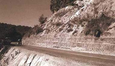
A recently rehabilitated road
pavement: its longevity depends on the protection and maintenance of the
adjoining slopes.
For some activities, legal questions may arise. A Guide to the Law regarding roadside vegetation is given in the companion Reference Manual.
In rural areas, the road neighbours ('local people') must be taken into consideration. The Department of Roads may be able to collaborate with them for mutual benefit. Section 5.5 gives a code of practice for collaboration with road neighbours and more detailed guidelines are given in the Reference Manual.
'Maintenance' of vegetation in engineering is equivalent to 'management' in forestry, horticulture and agriculture. Vegetation on roadsides must be maintained on a long-term basis in order to maximise their engineering contribution, productivity and appearance. Most operations are similar to normal forestry practices. However, there are some particular needs for bio-engineering which are specific to the road sector.
In general, routine maintenance activities can carried out by lengthmen and gangs should carry out preventative maintenance. However, the mode of operation depends on the scale of each site and should be kept flexible.
The timing of checking and intervention for each activity is given in Section 5.2.
General principles of vegetation maintenance

Well-maintained roadside slopes.
The vegetation is managed and cut on a regular basis
In bio-engineering, the aim is to stop all forms of erosion and shallow mass movement. It is usually necessary to manage vegetation in order to achieve this since a semi-natural (or unmanaged) community of vegetation does not always provide the functions required for engineering. Often, unmanaged vegetation leads to a dense canopy of trees with relatively little vegetation underneath. Although the trees have deep roots, they do not stop erosion on the surface. That is why soil erosion often takes place under natural or protected forests.
Mixed structure
You should aim to manage the vegetation to produce a mixed vegetation community1 with a variety of trees, shrubs and grasses on a single site. Single species, or vegetation communities dominated by one or a few species, are unlikely to have either an irregular structure or variety of ages.
1 A vegetation community can be defined as 'an established group of plants living more-or-less in balance with each other and their environment; the group can be either natural or managed'.
Mixed age
Try to achieve a collection of plants of mixed ages for each site (an uneven-aged structure). This means that all plants do not need to be replaced at the same time and there will always be some strong, healthy plants protecting the slope.
Low maintenance
Aim to establish a vegetation community that does not need too much intervention from outside to maintain it. For example, choose species that can regenerate naturally (without planting); species that do not grow too fast or too tall (need cutting and removal less frequently); species that live longer, etc.
Managed progression
In bio-engineering it is often necessary to start with pioneer species2 and move towards a climax community3. Examples of this include:
· tilka/dhanyero scrubland ® mixed sal forest (eventually ® mixed tropical hardwoods);
· khayer/sisau plantation ® mixed sal forest (eventually ® mixed tropical hardwoods);
· khote salla plantation ® mixed broad-leaved forest (tooni; chilaune; katus);
· utis plantation ® chilaune/katus forest;
· gobre salla plantation ® khasru/gurans forest.
2 Pioneer or colonising species are the first plants to appear on bare ground and are naturally adapted to living on sites with harsh conditions. Examples are: grasses: babiyo, dhonde, kans, khar; shrubs: areri, bhujetro, keraukose, saruwa; trees: bakaino, khayer, salla, sisau, utis.3 Climax community species are plants that can form permanent natural forest or natural vegetation. They tend to require better sites to grow, and grow more slowly. Examples are: grasses: amliso, dangre khar, padang bans; shrubs: bainsh, simali, sajiwan; trees: chilaune, katus, lankuri, sal.
5.2 Planning the maintenance of bio-engineering and other roadside vegetation
Vegetation and bio-engineering maintenance activities
It is important to plan the maintenance of roadside vegetation in order to ensure that the necessary work is carried out at the best time of year, and to avoid future problems resulting from lack of maintenance. Since each site requires its own maintenance budget, planning ensures that budgets are allocated in good time and priority work can be carried out.
Consider each site separately, because maintenance interventions are extremely site-specific for each slope. Consider the history and future plans for each site independently.
Each site has a different combination of conditions, which affects its maintenance, including:
· physical conditions (e.g. slopes, materials, local climate, existing vegetation, extent of site);
· legal position (e.g. land ownership, existence of disputes, distance from road, type of road);
· road neighbours (e.g. occupations, populations, level of interest and previous involvement in road maintenance, existing local groups such as forest user groups, NGOs, societies).

Figure 5.1: Maintenance activity
calendar
Before starting to plan, assemble as much information as you can on these three categories. A plan can then be prepared (and budgeted, if necessary) before starting the work.
Most maintenance operations are seasonal. The calendar in Figure 5.1 summarises the recommended timing for the operations described in these guidelines.
Planning the maintenance programme
Follow these steps to plan the maintenance of roadside support carefully.
Step 1
Identify the maintenance needs of vegetation on the roadside slopes. This should cover both vegetation planted under a bio-engineering programme, and other existing vegetation. This will entail a detailed survey of all slopes adjacent to your road section.
Step 2
Quantify the work that must be done regularly, as part of a yearly programme.
Step 3
Devise a programme of regular checks. This must state which sites are to be checked, when they are to be checked, what they are to be checked for, and who will do the checking.
Step 4
Implement the maintenance programme.
Step 5
Monitor the maintenance programme and evaluate its effectiveness. Improve it as necessary.
The table in Figure 5.2 specifies precisely the timing of interventions to maintain roadside support. These should be followed in every case.
Figure 5.2: Detailed timing of the maintenance activities for vegetation on roadside slopes
|
ACTIVITY |
CATEGORY |
SITES TO CHECK |
TIMING OF CHECKS |
TIMING OF ACTION |
|
Protection of planted sites |
Routine |
All roadside slopes. |
Carry out checks on 1 Baisakh and 1 Kartik.* If protection is given, make weekly inspections. |
Protect immediately, if necessary. |
|
Weeding |
Routine |
Sites where bio-engineering has been used in the past three years. |
Check on 1 Shrawan, 1 Bhadra and 1 Aswin.* |
Weed immediately, if necessary. |
|
Mulching |
Routine |
Sites where bio-engineering has been used in the past three years. |
Check on 1 Mangsir.* |
If mulching is necessary, start work on 1 Poush.* |
|
Grass cutting |
Routine |
All roadside slopes. |
Check on 1 Poush.* |
If grass cutting is necessary, start work on 1 Magh.* |
|
Watering |
Routine |
Only those sites where bio-engineering has been used within the past 12 months. |
Check weekly in Chaitra, Baisakh and Jestha. |
Water immediately, if necessary. |
|
Thinning of shrubs and trees |
Preventative |
All roadside slopes with forest cover and all sites where bio-engineering was used more than two years ago. |
Check on 1 Kartik.* |
If thinning is necessary, start work on 1 Poush.* |
|
Repair of vegetation structures |
Preventative |
All sites where bio-engineering has been used. |
Check on 1 Baisakh.* |
If repairs are necessary, start work on 1 Ashad.* |
|
Vegetation enrichment |
Preventative |
All roadside slopes. |
Check on 1 Baisakh.* |
If enrichment is necessary, start work on 1 Ashad.* |
|
Removal of unwanted trees |
Preventative |
All roadside slopes. |
Check on 1 Kartik.* |
If removal is necessary, start work on 1 Poush.* |
* Or on the first working day after this date.
5.3 Routine bio engineering maintenance activities
Protection of planted sites
Why protect?
People may cut grasses, shrubs or trees too much, or at the wrong time of year. This can stunt growth and prevent plants from fulfilling their functions. If plants are cut before the seeds fall, there will be less natural regeneration, especially from grasses. However, at certain times, local people can be very helpful.
Animals may eat small plants and damage the slope with their hooves. Animals are very difficult to control if they are allowed on to a site.
How to protect slopes
Planted sites can be protected in one of four main ways.
· A warden1 can be employed to watch the site. If this is done, he or she should be told also to do weeding, mulching and other work, rather than just to walk around watching the site. This would need encouragement from the Engineer, Overseer and Supervisor.· Protection after planting can be made a compulsory part of a contract package. However, this can be used for only 6 to 12 months.
· The protection of roadside sites can be made part of a road lengthman's duty. In certain cases it may be necessary to reduce the length of road covered by the lengthman.
· An arrangement can be made with local people to protect the area. This is often the most long-lasting, but is also the hardest to achieve. It can be done only if there is a clear incentive for the people involved, such as providing large quantities of fodder from the road reserve. This is considered in more detail in the Reference Manual.
1 The function of a warden is more than that of a chowkidar or heralu. He or she has to carry out a number of maintenance activities.
Whatever system is used, it is very important that both the areas to be protected and the duties to be performed are clearly defined. The Division staff must ensure that the people doing the protection really understand what is expected of them. The box below gives an example of the duties that a site warden should be expected to perform.
How to check that sites are adequately protected
Basic checks can be made easily by walking through a site that is being protected and looking for signs of damage. Do not just walk along a main path but also go into some other corners of the site. The signs to look for are:
· regular spacing and growth of plants;
· plants are carefully weeded and mulched;
The following signs suggest poor protection:
· physical damage to plants (e.g. growing shoots or leaves eaten off);
· animals or signs of animals (e.g. dung) in the area.
|
DUTIES OF WARDENS IN PROTECTING PLANTED SITES IN ROADSIDE AREAS (EXAMPLE) Site wardens should be active in a range of duties, including: · watching all sites (in their road section) and ensuring that no domestic or wild animals graze the areas; The warden should be given the best possible support from the Division. This should be as for lengthmen. Local wardens are often the most effective in reducing damage. This seems to be partly because they know personally all the people who use the area. See also Standard Specifications for Bio-engineering, item 2881, 'provision and role of site watchmen' (given in the Reference Manual). |
Weeding
What is weeding?
Weeding is the removal of unwanted vegetation that is competing with the growth of the desired plants.
Why do weeding?
· To improve the growth of the desired species by removing competing vegetation. In some dry forest types, it may also be necessary to reduce the risk of fires.· To remove dense vegetation (especially invasive weeds such as ban mara and tite pate) in order to allow more desirable plants to regenerate naturally.
· To improve drivers' sight lines and the visibility of pedestrians, where these have been reduced.
When should weeding be done?
When the plantation age is young, and also in older sites when there is a need to encourage better growth or natural regeneration.
Weeding is normally required only during the monsoon rains, once unwanted plants have grown up. The most important time is from Shrawan to Aswin.
How to weed a site
Select individual sites according to their situation and treat them at one time.
Carefully cut and remove only undesirable species, but take care to retain plants of the desired species. Always avoid deep soil working, which can damage plant roots.
Small plants with weak, shallow roots, such as ban mara (Eupatorium adenophorum) and tite pate (Artemisia vulgaris) can simply be pulled up if this will not damage the remaining plants. Unwanted plants with stronger roots should be cut about 50 mm above ground level using a hasiya (sickle).
Products from weeding
Weeding can produce material for mulching or composting, and sometimes for fodder.
Materials and tools for weeding
Most weeding operations will only require a hasiya (sickle).
Mulching
What is mulching?
Mulching is the positioning of inert dead vegetation around seedlings to keep the soil cool and moist. Mulch is usually made by cutting up the stems and leaves of unwanted plants
Why do mulching?
Mulching is required to improve the growth of plants less than three years old.
By keeping the soil cool and moist, mulching increases the rate of growth. Plants become big more quickly and their roots help to strengthen the slope.
Where grass seeding has been done, mulching also protects delicate new grass plants from both scorch by hot sun and damage by rain splash.
When should you mulch?
Mulching is most needed when there is too much sun and too little water. This means any time during the dry season and early rains, from Poush to Ashad.
All new shrub and tree seedlings should be mulched directly after planting.
How to mulch
Mulch can be made from the stems and leaves of any plants. It is important not to use plant parts carrying seeds, as this will lead to a big weeding problem.
If possible, make mulch from annual and perennial weeds with poor rooting characteristics, such as ban mara (Eupatorium adenophorum) and tite pate (Artemesia vulgaris). The greenery should be collected when there is most material available, but before it forms seeds. This is most often in Shrawan and Bhadra. However, requirements always have to be assessed specifically and local sources checked.
Straw and thatch grasses can also be used.
Collected material should be chopped: the maximum size is 150 mm. It can be stored until required if necessary.
Spread the mulch around the plant being treated in a layer 50 mm to 100 mm thick. A circle of radius 150 mm should be left next to the plant itself. Outside this, the mulch should form a circle of about 750 mm radius.
Materials and tools for mulching
Most mulching operations will require:
a hasiya (sickle) for cutting the plants;
a khukuri for chopping the weeds into small pieces;
a doko and namlo for transporting the mulch.
Grass cutting
Why cut grasses?
· Cutting grasses encourages them to remain vigorous and to put out new shoots. It also allows better inspection of slopes and provides useful products.· To improve drivers' sight lines and the visibility of pedestrians, where these have been reduced.
When should grasses be cut?
Grasses are cut once a year, after the seeds have fallen. This means that cutting must not take place before the beginning of Magh. Grasses should be cut on all accessible bio-engineering sites and other roadside slopes with grass cover.
Grass cutting can take place any time during Magh and Falgun. If the grasses impede road traffic at other times, they should be cut immediately.
Fodder grasses (but not tree fodder or dale ghans), which are not commonly planted in roadside areas, should be cut every one to two months during the wet season. Cutting should be done whenever a good crop can be taken.
How to cut grasses
Cut grasses about 150 mm above the ground, using a karauti or hasiya (sickle). Care must be taken not to pull out the roots of the grass clump. Also, other plants must not be damaged; especial care must be taken of small shrub and tree seedlings.
Products from grass cutting
Any cut grass can be used for mulching the plants on the site.
Otherwise, the cut grass can be used for thatching, fodder, fibres, kuchos or other uses, according to the species. Government regulations must be followed for the disposal of products grown on road reserve land. Products from other land should normally be given to the land owner or community group responsible for the land.
Materials and tools for grass cutting
Most grass cutting operations will only require a karauti or hasiya (sickle).
Watering
Why do watering?
Watering1 can help enormously to improve the growth of plants on harsh sites during the later dry season (Chaitra to Jestha). If watering is done, mulching is normally done as well.
1 Note: watering of plants is only required in special cases. It is most commonly used on critical sites where planting is carried out well before the monsoon, such as in Baisakh or Jestha.
When should you water?
Watering is done only in these situations:
· on all bamboos planted in dry sites;· on critical sites, where good plant cover must be established before the start of the monsoon rains; or
· when water is easily available on site, such as from a nearby khola or a spring; or
· when a dry period occurs soon after planting in the early monsoon, and resources allow; or
· where a warden has no other duties and water is available close to the site.
Watering is done on days without rain, normally in Chaitra, Baisakh and Jestha. It is done in the morning or evening. It is not done during the middle of the day when it is sunny (because too much would evaporate).
How to water
Water must be applied slowly and allowed to infiltrate, preferably using a sprinkler. It must not run off. If necessary, the ground can be lightly cultivated to increase infiltration. For shrub and tree seedlings, the water can be poured into a small trench just up the slope.
|
Watering rates: |
|
|
grass plants: |
0.25 litres per plant per day; |
|
shrub and | |
|
tree seedlings: |
5 litres per plant per day; |
|
bamboo plants: |
10 litres per plant per day. |
Materials and tools for watering
If possible, water should be brought by pipe. Otherwise, it can be carried in buckets or watering cans.
5.4 Preventative maintenance of roadside vegetation
Pruning and thinning of shrubs and trees
A detailed technical appraisal of pruning and thinning is given in the Reference Manual: that should be followed for large sites and in special cases. However, this section gives guidelines applicable to most sites, and most maintenance requirements.
What are pruning and thinning?
Pruning is the removal of the lower branches of a tree or large shrub.
Thinning means removing selected shrubs or trees to decrease the density of the plants. In practice, this usually means removing about half the number of trees on the site.
There are three forms of thinning:
· pollarding: a tree is cut 2 to 3 metres above the ground and new shoots grow up;
· coppicing: a tree is felled and new shoots come from the stump;
· selection thinning: a tree is felled and the stump allowed to die.
Most thinning operations involve selection thinning: i.e. the removal of whole trees.
Why do pruning and thinning?
· To increase the light penetrating through the canopy. This will improve the plants growing on the ground underneath, especially grasses, and reduce surface erosion.· To remove trees of species that are no longer required in the final, mature site.
· To improve drivers' sight lines and the visibility of pedestrians, where these have been reduced.
When should you prune and thin?
When a plantation is dense and shrubs or trees have crowns that are touching. This may be about every five years, but every site should be inspected annually.
Shrubs and trees are best removed during the winter (Poush to Falgun) when disturbance is least likely to hinder the growth of the remaining plants.
How to prune and thin
· Start by pruning. First cut off the bottom branches, up to half the total height of the shrub or tree. For large mature trees only, cut branches up to two-thirds the total height of the tree.· Cut branches cleanly and as close to the trunk as possible without causing damage. Cut the branches nearest the ground first and move upwards.
· Use sharp tools to cut branches. Where the branch is more than 50 mm in diameter, make a small cut underneath the branch first. The bark should never be torn: this can damage the plant badly.
Now ask this question:
Has the canopy been opened enough just by pruning, so that there is now enough light penetrating to allow grasses to grow under the trees?
If 'yes', then the operation is complete.
If 'no', then thin the trees.
Thinning is carried out by following this procedure.
· Inspect the site carefully and decide which trees should be kept and which trees should be removed.
· Choose to keep vigorous, healthy trees that will continue to grow well if they are given more space.
· As you choose the trees to be felled, select them in this order:
1. All dead, dying or seriously damaged trees.
2. Trees of unwanted species.
3. Trees of bad shape and large crown.
4. Next, select trees to leave a variety of sizes and ages.
· Mark with paint the trees that should not be felled.
· Fell the unmarked trees.
· Thin a site according to its requirements, to achieve 50 to 67 per cent open space and only 33 to 50 per cent canopy.
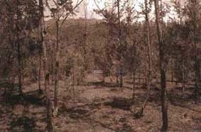
An open canopy with grasses
growing underneath.

Too little light is penetrating
this canopy to allow grasses to grow; pruning or thinning is required

A plantation of utis (Alnus
nepalensis) where the trees are thin and weak due to dense planting and
intense competition for light. Pruning and thinning are required to improve the
spacing, as well as to allow better understorey vegetation to develop
Products from pruning and thinning
Firewood is the main product from pruning operations, but very little will be produced from plants that have been regularly pruned for several years.
A range of sizes of poles will be produced from thinning, suitable for many uses (building, fences, etc.). However, much of the cut material will be suitable only for firewood if plants are not straight, or if they are unsuitable for timber.
Government regulations must be followed for the disposal of products grown on road reserve land. Products from other land should normally be given to the land owner or community group responsible for the land.
The Department of Roads can heat bitumen with firewood from trees grown in the road reserve.
Materials and tools for pruning and thinning
Most pruning operations require a khukuri, secateurs or small saw.
Most thinning operations require a saw or axe.
Paint for marking trees that will not be thinned or pruned.
Use very sharp tools; working with blunt tools can damage trees.
Repair of vegetation structures
What is the repair of vegetation structures?
The repair of any form of bio-engineering treatment: mainly palisades, fascines and brush layering, and re-turfing. This should be done as and when required.
Why repair vegetation structures?
To maintain the effectiveness of the treatments and to ensure that they become stronger over time.
When should vegetation structures be repaired?
Bio-engineering sites should be checked regularly. This should normally be once every six months or less.
Repairs should be programmed as part of the Division's work plan.
Repairs to living structures should be done during the monsoon rains (i.e. Ashad to Bhadra).
How to repair vegetation structures
Employ a small specialist gang to repair bio-engineering treatments.
The minimum amount of disturbance should be made to the site.
The work to be done depends on the particular bio-engineering treatment and the type of damage.
A suitable lengthman or site warden can undertake very small repairs.
Materials and tools for repairing vegetation structures
These are normally the same as for the original construction of the structure being repaired. The materials and tools required are given in the appropriate rate analysis norms.
Vegetation enrichment
What is vegetation enrichment?
Vegetation enrichment means planting more grasses, shrubs or trees within the site area or in gaps within the existing vegetation.
It can also involve the planting of shrubs and trees to replace those removed for certain reasons (see below).
Why enrich vegetation?
To establish more plants in places where there are gaps.
To introduce or change the species composition on a site: for example to increase the range of species or to move away from a single species (e.g. utis), by planting seedlings of other species.
When should vegetation be enriched?
· Whenever there are gaps in the vegetation in which erosion might start.· When it is necessary to change the mixture of species. This might be to move from pioneer to climax community species (following the principles described in the Reference Manual.
· When trees that have had to be removed need replacing. This is when the other remaining vegetation is not adequate to protect the slope.
· Actual enrichment planting should be done during the monsoon rains (i.e. Ashad to Bhadra).
How to enrich vegetation
Carefully select plants that are desired on the site and should grow well, and raise them in the nursery
Plant only in gaps, not under a dense forest canopy. Follow this with regular weeding.
Spread the planting over several years and concentrate on successful establishment in a small area each year, if the total area available for planting is large.
Vegetation enrichment is best combined with other operations that increase the amount of light penetrating the canopy (such as thinning and tree removal). In this case, enrichment should be concentrated in gaps or open areas in the canopy.
Materials and tools for vegetation enrichment
These are normally the same as for the original planting of the vegetation being enriched. The materials and tools required are given in the appropriate rate analysis norms.

Thinning roadside plantations can
yield significant volumes of firewood
Removal of unwanted shrubs and trees
Why remove unwanted shrubs and trees?
A tree may be removed for any of the following reasons:
· The tree is dead and may fall down.· The tree is obstructing traffic or drivers' sight lines.
· The tree is surcharging a steep slope, or is too big and unstable for the slope on which it is growing.
· The tree needs to be cut as part of a thinning programme. This will allow more light to penetrate and help the understorey grow.
· The tree needs to be cut to allow coppice shoots to come from the stump.
· The tree needs to be cut to allow widening of the road.
When should unwanted shrubs and trees be removed?
Whenever a problem occurs where a tree needs to be removed.
If possible, shrubs and trees are best removed during the winter (Poush to Falgun) when the disturbance is least likely to hinder the growth of the remaining plants.
How to remove unwanted shrubs and trees
Follow the legal guidelines shown in the Reference Manual.
Organise labourers or a contractor to fell the shrub or tree and dispose of the produce according to regulations.
Large trees should be felled so that they do not damage young trees and shrubs unduly. If a tree with a very large crown has to be felled, it should be pruned first to remove the crown branches. It should also be felled across the slope to avoid excessive damage.
Materials and tools for the removal of unwanted shrubs and trees
Most removal operations require the same tools as for thinning. These are: a saw, or an axe, and paint for marking trees to be left. All tools used should be very sharp. This is to avoid damage to trees from bad working with blunt tools.

A positive relationship with road
neighbours is advantageous for all concerned
|
A CODE OF PRACTICE CONCERNING ROADS AND OTHER LAND USES 1. This is a practical guide which, if followed by Departmental staff, will help to ensure that roads do not conflict with other land uses. It will also help to improve relationships with rural road neighbours ('local people'). 2. The impact of every operation on the surrounding land must be considered before it is undertaken. A full site investigation must be made. Consideration must be given to the potential for damage to surrounding farmland. 3. No operation should be permitted (without due compensation) that gives rise to damage to farmland, water supply lines, irrigation systems, or other forms of local infrastructure. 4. Where there is likely to be any adverse impact or conflict, then contact should be made with the people concerned. Adequate time must be allowed for discussion and agreement. Possible alternatives should be considered. 5. In every case, the requirements of the law should be followed where compensation may be due. 6. On every road section, a number of safe tipping sites must be designated. All staff must be instructed to use them. Such sites must be away from houses and farmland; they must be on stable slopes; and they must be well marked on the lower side. 7. No tipping of material should be permitted anywhere except in designated tipping sites. 8. The discharge of all drains should be checked on a recurrent basis. Any damage resulting from excess flows should be rectified. 9. Any changes (e.g. small landslides) to roadside slopes that might affect either the road or adjoining land should be investigated promptly. Repairs, if necessary, should be undertaken at the earliest opportunity. 10. Any complaint by a road neighbour should be investigated promptly and action taken as necessary. 11. Where a road neighbour is undertaking activities causing damage to the road, a thorough investigation should be made. This should start from a sympathetic approach, but where the Department's interests are affected, reference should be made to the laws. The legal standing of the Department of Roads should be ascertained as early as possible in each particular instance. 12. Where there is a conflict, a compromise solution that suits both parties should be sought wherever possible. |
5.5 Liaison with rural road neighbours
Roads should blend with the landscape through which they pass. They should not be permitted to show a negative impact on other land uses. In rural areas, they must enhance agriculture, and not have a damaging effect on the activities of farmers. A positive relationship between road maintenance offices and the people who live beside their roads is advantageous for everyone.
To move in this direction, the code of practice given above should be followed for reasons of good technical working, good professionalism and good ethics. It applies specifically to roadside maintenance, rather than to the construction of new roads.
|
| ||||||||||||||||||||||||||||||||||||||||||||||||||||||||||||||||||||||||||||||||||||||||||
Annex A - Site assessment pro forma
Complete one pro forma per site. Use additional forms if there are more than three segments on the site
|
Site location and chainage: | | | |
|
Date of assessment: |
Assessor's name: |
| |
|
Sketch of site |
| |
[Label segments] |
| |
| | |
| |
| | |
| |
| | |
|
Scale: | |
Orientation: |
|
|
Segment number |
(1) |
(2) |
(3) |
|
(a) Erosion and failure processes | | | |
|
(b) Other factors |
| | |
|
(c) Slope angle(s) |
| | |
|
(d) Slope length |
| | |
|
(e) Material drainage | | | |
|
(f) Segment moisture |
| | |
|
(g) Altitude |
| | |
Assessment criteria. See Roadside Bio-engineering Site Handbook, Annex A, pages 127-129 for details
|
(a) |
Erosion and failure processes. |
List the erosion or failure processes. State their size and severity. |
|
(b) |
Other factors. |
List any physical factors that might affect the site. State their size and severity. |
|
(c) |
Slope angle(s). |
Measure and place in one of 3 classes: <30°, 30 - 45°, or >45°. |
|
(d) |
Slope length. |
Measure and place in one of 2 classes: <15 metres or >15 metres. |
|
(e) |
Material drainage. |
Assess and place in one of 2 classes: good or poor. |
|
(f) |
Segment moisture. |
Assess and place in one of 4 classes: wet, moist, dry or very dry. |
|
(g) |
Altitude. |
Determine: ± 100 metres. Use an altimeter, map or site drawing. |
Figure A1: The main erosion and failure processes
|
MECHANISM |
DESCRIPTION |
|
Erosion on the surface |
Rills and small gullies form in weak, unprotected surfaces. Erosion should also be expected on bare or freshly prepared slopes. |
|
Gully erosion |
Gullies that are established in the slope continue to develop and grow bigger. Large gullies often have small landslides along the sides. |
|
Planar sliding |
Mass slope failure on a shallow slip plane parallel to the surface. This is the most common type of landslide, slip or debris fall. The plane of failure is usually visible but may not be straight, depending on site conditions. It may occur on any scale. |
|
Shear failure |
Mass slope failure on a deep, curved slip plane. Many small, deep landslides are the result of this process. Large areas of subsidence may also be due to these. |
|
Slumping or flow of material when very wet |
Slumping or flow where material is poorly drained or has low cohesion between particles and liquefaction is reached. These sometimes appear afterwards like planar slides, but are due to flow rather than sliding. The resulting debris normally has a rounded profile. |
|
Debris fall or collapse |
Collapse due to failure of the supporting material. This normally takes the form of a rock fall where a weaker band of material has eroded to undermine a harder band above. These are very common in mixed Churia strata. |
|
Debris flow |
In gullies and small, steep river channels (bed gradient usually more than 15°), debris flows can occur following intensive rain storms. This takes the form of a rapid but viscous flow of liquefied mud and debris. |
(a) Erosion and failure processes
A number of erosion and failure processes are to be found. The types of erosion and slope failure found in Nepal are given in Figure A1. All sites have a combination of these mechanisms at work on them. During site assessment, you should check for these.
Figure A2: The main physical factors affecting slopes
|
POTENTIAL FACTOR |
DESCRIPTION |
|
Fault lines |
Small fault lines may cause differential erosion in parts of the site. |
|
Springs |
There may be seasonal springs within the site, which cause localised problems of drainage or slumping. |
|
Slip planes |
The main plane of failure may not be the only one. Many sites have secondary, smaller slip planes additional to the main failure mechanism |
|
Large gullies |
Large gullies nearby may erode backwards and damage the site. Alternatively, they may discharge on to the site, causing deposition there. |
|
Landslides |
Nearby landslides may extend headwards or sideways, or may supply debris on to the site. |
|
River flooding |
A large river below the site may flood badly, damaging the site by either erosion or deposition, or a combination of both. |
|
River cutting |
Rivers below the site may move in floods, undercutting the toe of the site. |
|
Catchments |
If there is an extended catchment area above the site, it could lead to a large discharge, which causes bad damage by erosion or deposition. |
|
Drain discharge |
The discharge of drainage water must be safeguarded to avoid causing erosion or mass failures. Poorly sited or inadequately protected discharge points can cause severe problems. |
|
Khet and kulos |
Khet (rice paddy) land or a kulo (irrigation leat) above a site usually means a large volume of water infiltrating into the slope, with a greater potential for failure or large-scale erosion. |
|
Construction activities |
Construction activities on or near the site may lead to undermining through excavations, or surcharging through spoil disposal in the wrong places. |
(b) Other factors
In addition to erosion and failure mechanisms, other factors may affect the site. Some are internal (e.g. springs) while others are external (e.g. river undercutting). During site assessment, you must check for signs of any of the potential damaging factors listed in Figure A2.
(c) Slope angle(s)
Measure the average slope angle of the slope segment and place it in one of three classes:
< 30º,
30 - 45°, or
> 45°.
If there is more than one dominant slope, record all main slope angles.
Figure
(d) Slope length
Measure the average length of the slope segment and place it in one of two classes:
< 15 metres or
> 15 metres.
Figure A3: Common features indicating soil drainage characteristics
|
MATERIAL DRAINAGE |
TENDENCY TOWARDS GOOD DRAINAGE |
TENDENCY TOWARDS POOR DRAINAGE |
|
Overall drainage |
Freely draining material; dries quickly after rain storms |
Slowly draining material; tends to remain wet for long periods after rain; behaves like firm dahi |
|
Soil particle size |
Coarse textures; loams and sandy soils |
Fine textures; clays and silts |
|
Porosity |
Large inter-connecting pores |
Small pores |
|
Material types |
Stony colluvial debris; fragmented rock; sandy and gravelly river deposits |
Residual soils of fine texture; debris from mud flows, slumps, etc. rato mato |
|
Slope types |
Fill slopes; cut slopes in stony debris (colluvium) |
Cut slopes in original consolidated ground |
(e) Material drainage
Assess and place in one of two classes: good or poor (see Figure A3).
Figure A4: Environmental factors determining site moisture
|
SITE MOISTURE FACTOR |
TENDENCY TOWARDS DAMP SITES |
TENDENCY TOWARDS DRY SITES |
|
Aspect |
Facing N, NW, NE and E |
Facing S, SW, SE and W |
|
Altitude |
Above 1500 metres; particularly above 1800 metres |
Below 1500 metres; deep river valleys surrounded by ridges |
|
Topographical location |
Gullies; lower slopes; moisture accumulation and seepage areas |
Upper slopes; spurs and ridges; steep rocky slopes |
|
Regional rain effects |
Eastern Nepal in general; the southern flanks of the Annapurna Himal |
Most of Mid Western and Far Western Nepal |
|
Rain shadow effect |
Sides of major ridges exposed to the monsoon rain-bearing wind |
Deep inner valleys; slopes sheltered from the monsoon by higher ridges to the south |
|
Stoniness and soil moisture holding capacity |
Few stones; deep loamy* and silty soils |
Materials with a high percentage volume of stones; sandy soils and gravels |
|
Winds |
Sites not exposed to winds |
Large river valleys and the Terai |
|
Dominant vegetation |
e.g. utis, katus, chilaune, amliso, nigalo, bans, lali gurans |
e.g. khayer, babiyo, khar, dhanyero, salla, imili, kettuke |
* Loam is the name given to a soil with moderate amounts of sand, silt and clay, and which is therefore intermediate in texture and best for plant growth.
(f) Segment moisture
Assess and place in one of four classes:
|
Wet: |
permanently damp sites (e.g. north-facing gully sites). |
|
Moist: |
sites that are reasonably well shaded or moist for some other reason. |
|
Dry: |
generally dry sites. |
|
Very dry: |
sites that are very dry; these are usually quite hot as well (e.g. south-facing cut slopes at low altitudes). |
See Figure A4.
(g) Altitude
Determine: ±100 metres. Use an altimeter, map or site drawing.
|
| ||||||||||||||||||||||||||||||||||||||||||||||||||||||||||||||||||||||||||||||||||||||||||
Annex B - Full lists of species for bio-engineering in the road sector
B1: FULL LISTS OF SPECIES FOR BIO-ENGINEERING IN THE ROAD SECTOR
GRASSES FOR BIO-ENGINEERING IN THE ROAD SECTOR (including small legumes)
|
Local name |
|
Botanical name |
Rec |
Character |
Altitude |
Sites |
Best propagation |
Seed collection |
Comments |
|
Amliso |
|
Thysanolaena maxima |
|
Large clumping |
Terai - 2000 m |
Varied |
Slip cuttings |
Mar-Apr |
Best in damper areas |
|
Babiyo |
|
Eulaliopsis binata |
|
Medium-sized clumping |
Terai - 1500 m |
Hot and dry |
Slip cuttings/seeds |
Jan-Feb | |
|
Bansko ghans |
|
Eragrostis tenella | |
Large spreading |
500 - 1800 m |
Varied |
Slip cuttings/seeds |
Dec-Jan | |
|
Blue panic grass |
|
Panicum antidotate | |
Medium-sized spreading |
500 - 1800 m |
Varied and dry |
Slip cuttings |
Use cuttings |
High grazing risk |
|
Buffalo grass |
|
Cenchrus ciliaria | |
Medium-sized spreading (exotic) |
500 - 1800 m |
Varied and dry |
Slip cuttings |
Use cuttings |
High grazing risk |
|
Clover |
|
Trifolium species | |
Small spreading legume (exotic) |
Terai - 2000 m |
Varied; moist |
Stem cuttings/seeds |
Use cuttings |
High grazing risk |
|
Dangre khar |
|
Cymbopogon pendulus | |
Large clumping |
Terai - 1200 m |
Varied |
Seeds |
Dec-Jan |
Best in damper areas |
|
Desmodium |
|
Desmodium distortum | |
Spreading legume (exotic) |
Terai - 1800 m |
Varied |
Stem/slip cuttings |
Use cuttings |
High grazing risk |
|
Desmodium greenleaf |
|
Desmodium intortum | |
Spreading legume (exotic) |
Terai - 2000 m |
Varied and dry |
Stem/slip cuttings |
Use cuttings |
High grazing risk |
|
Dhonde |
|
Neyraudia reynaudiana |
|
Large clumping |
Terai - 1500 m |
Hot and dry |
Stem/slip cuttings/seeds |
Dec-Jan |
15,520,000 seeds/kg |
|
Dubo |
|
Cynodon dactylon | |
Small creeping |
Terai - 1800 m |
Varied |
Stem cuttings |
Use cuttings |
|
|
Dhungre |
|
Unknown | |
Large clumping |
1500 - 2500 m |
Damp or shady |
Large slip cuttings |
Dec-Jan | |
|
Dhus |
|
Unknown | |
Large clumping |
1500 - 2500 m |
Varied, dry to moist |
Slip/stem cuttings |
Dec-Jan | |
|
Jaughans |
|
Unknown | |
Medium-large spreading |
1600 - 3000 m |
Varied |
Slip cuttings/seeds |
May-Jun | |
|
Kagati ghans |
|
Cymbopogon citratus | |
Medium-large clumping |
Terai - 1500 m |
Varied |
Slip cuttings/seeds |
Nov-Dec | |
|
Kans |
|
Saccharum spontaneum |
|
Large clumping and spreading |
Terai - 2000 m |
Hot and dry to moist |
Slip cuttings |
Nov-Dec |
Very tough on all sites |
|
Katara khar |
|
Themeda species |
|
Large clumping |
Terai - 2000 m |
Varied |
Slip cuttings/seeds |
Oct-Nov | |
|
Khar |
|
Cymbopogon microtheca |
|
Medium-large clumping |
500 - 2000 m |
Hot and dry; varied |
Slip cuttings/seeds |
Dec-Jan |
1,681,000 seeds/kg |
|
Khus |
|
Vetiveria lawsoni |
|
Medium-large clumping |
Terai - 1500 m |
Varied |
Slip cuttings |
Sep-Nov |
Fill slopes only; |
|
Kikiyu, thulo dubo |
|
Pennisetum clandestinum | |
Small creeping (exotic) |
Terai - 1800 m |
Varied |
Stem/slip cuttings |
Use cuttings |
High grazing risk |
|
Kudzu |
|
Pueraria lobata | |
Spreading legume (exotic) |
500 - 1500 m |
Varied |
Stem/slip cuttings |
Use cuttings |
High grazing risk |
|
Molasses |
|
Melinis minutiflora | |
Medium-large spreading (exotic) |
Terai - 1800 m |
Varied to dry |
Slip cuttings/seeds |
Use cuttings |
High grazing risk |
|
Musekharuki |
|
Pogonatherum paniceum (?) | |
Small spreading |
Terai - 2500 m |
Varied |
Slip cuttings |
Use cuttings |
|
|
Napier |
|
Pennisetum purpureum | |
Large semi clumping (exotic) |
Terai - 1750 m |
Varied; needs fertile soil |
Stem cuttings |
Use cuttings |
High grazing risk |
|
Narkat |
|
Arundo clonax |
|
Large clumping and spreading |
Terai - 1500 m |
Hot and dry; varied |
Stem/slip cuttings |
Nov-Jan | |
|
NB21 |
|
P. Purpureum x typhoides | |
Spreading (exotic) |
Terai - 1750 m |
Varied |
Stem cuttings |
Use cuttings |
High grazing risk |
|
Padang bans |
|
Himalayacalamus hookerianus |
|
Large clumping |
1500 - 2500 m |
Moist |
Large slip cuttings |
Use cuttings |
High grazing risk |
|
Phurke |
|
Arunduella nepalensis |
|
Medium-sized clumping |
700 - 2000 m |
Varied; stony |
Slip cuttings/seeds |
Dec-Jan |
1,809,000 seeds/kg |
|
Rato kans |
|
Frianthus rufipilus | |
Medium-sized clumping |
900 - 2200 m |
Varied |
Slip cuttings/seeds |
Dec-Jan | |
|
Salimo khar |
|
Chrysopogon gryllus | |
Medium-large clumping |
800 - 2000 m |
Varied |
Slip cuttings/seeds |
Dec-Jan | |
|
Setaria |
|
Setaria anceps | |
Medium-large spreading (exotic) |
500 - 2500 m |
Varied to dry |
Slip cuttings/seeds |
Jul-Aug |
High grazing risk |
|
Sito |
|
Neyraudia arundinacea |
|
Large clumping |
Terai - 1500 m |
Varied |
Slip cuttings/seeds |
Dec-Jan |
Higher rainfall areas; |
|
Stylo |
|
Stylosanthes guianensis | |
Spreading legume (exotic) |
500 - 1500 m |
Varied |
Stem/slip cuttings |
Use cuttings |
High grazing risk |
|
Thulo kharuki |
|
Capipedium assimile (?) | |
Medium-large clumping |
600 - 2000 m |
Varied |
Slip cuttings/seeds |
Dec-Jan |
Higher rainfall areas |
|
Tite nigalo bans |
|
Drepanostachyum intermedium |
|
Large clumping |
1000 - 2500 m |
Varied |
Large slip cuttings |
Use cuttings |
Drier sites than padang |


Rec:= particularly recommended for roadside areas.
B2: FULL LISTS OF SPECIES FOR BIO-ENGINEERING IN THE ROAD SECTOR
SHRUBS; SMALL TREES FOR BIO-ENGINEERING IN THE ROAD SECTOR
|
Local name |
|
Botanical name |
Rec |
Character |
Altitude |
Sites |
Best propagation |
Seed collection |
Seeds/kg |
Viability |
Comments |
|
Aak |
|
Calatropha giganteum | |
Small shrub, large fleshy leaves |
Terai - 1000 m |
Hot and dry; harsh |
Seeds/polypots |
Feb-Mar |
About 500,000 |
6 | |
|
Ainselu |
|
Rubus ellipticus | |
Thorny shrub up to 2 m high |
1000 - 2500 m |
Varied |
Seeds/root cuttings |
Nov-Dec |
About 50,000 |
6 | |
|
Alainchi |
|
Elettaria cardomomum | |
Herb up to 2 m high |
1000 - 2000 m |
Moist |
Seeds/polypots |
? |
- |
- |
Bears heavy shade |
|
Amala |
|
Phyllanthus emblica | |
Small tree |
Terai - 1500 m |
Hot and dry; harsh |
Seeds/polypots |
Sep-Jan |
- |
- |
Coppices well |
|
Amba/ambak |
|
Psidium guajava | |
Small tree, up to 5 m |
Terai-2000 m |
Varied and dry |
Seeds/polypots |
Aug-Oct |
About 10,000 |
12 | |
|
Aparajita |
|
Clitoria ternatea | |
Climbing shrub (exotic) |
Terai - 1500 m |
Varied and dry |
Seeds |
? |
- |
- |
Legume; high grazing risk |
|
Areri |
|
Acacia pennata |
|
Small thorny tree, up to 5 m |
500 - 1500 m |
Hot and dry; harsh |
Seeds/polypots |
Nov-Dec |
36,000 |
12 |
36,000 seeds/kg |
|
Argali |
|
Unknown | |
Shrub up to 3 m high |
1500 - 2500 m |
Varied, dry to moist |
Hardwood cuttings |
Use cuttings |
- |
- |
Not used as a fodder |
|
Arile kanda |
|
Caesalpinia decapetala | |
Thorny climber (exotic) |
Terai - 1500 m |
Varied |
Seeds/stem cuttings |
? |
- |
- | |
|
Armalito, |
|
Hippophae salicifolia | |
Small thorny tree |
1000 - 2500 m |
Varied and dry |
Seeds/polypots |
Aug-Nov |
130,000 |
12 |
Strongly promoted for |
|
Asuro |
|
Adhatoda vasica |
|
Shrub up to 3 m high |
Terai - 1000 m |
Varied |
Hardwood cuttings |
Use cuttings |
- |
- | |
|
Bains |
|
Salix tetrasperma |
|
Tree up to 15m high |
Terai-2700 m |
Moist |
Hardwood cuttings |
Use cuttings |
- |
- |
High grazing risk; |
|
Bains |
|
Unknown; not Salix | |
Shrub up to 5 m high |
1300 - 2000 m |
Varied to moist; |
Hardwood cuttings |
Use cuttings |
- |
- | |
|
Baganbeli/ |
|
Bougainvillea spectabilis | |
Thorny climber (exotic) |
Terai - 1500 m |
Varied and dry |
Stem cuttings |
Use cuttings |
- |
- | |
|
Ban chutro |
|
Berberis aristata | |
Thorny shrub up to 2 m high |
1500 - 3000 m |
Varied and dry |
Seeds/polypots |
? |
- |
- | |
|
Ban silam |
|
Elsholtzia blanda | |
Shrub |
Terai - 1500 m |
Varied |
? |
? |
- |
- | |
|
Bayer |
|
Zizyphus mauritiana | |
Thorny shrub up to 4 m high |
Terai - 1200 m |
Hot and dry; harsh |
Seeds/polypots |
Dec-Mar |
1,000 |
24 | |
|
Bhimsenpati |
|
Buddleja asiatica | |
Shrub up to 4 m high |
600 - 1800 m |
Hot and dry; harsh |
Seeds/hardwood cuttings |
Use cuttings |
- |
- | |
|
Bhui katahar |
|
Ananas comosus | |
Thorny herb up to 1 m high |
Terai - 1600 m |
Hot and dry; harsh |
Stem cuttings |
Use cuttings |
- |
- | |
|
Bhujetro |
|
Butea minor |
|
Shrub up to 4 m high |
500-1500 m |
Hot and dry; harsh |
Direct seeding |
Nov-Jan |
450 |
18 |
450 seeds/kg, |
|
Bilaune |
|
Maesa chisia |
|
Shrub |
Terai-2000 m |
Varied |
? |
? |
- |
- | |
|
Bokshi ghans |
|
Mimosa rubicaulis | |
Shrub up to 3 m high |
500 - 1700 m |
Varied |
Hardwood cuttings/seeds |
Use cuttings |
- |
- | |
|
Chiya |
|
Camellia sinensis | |
Shrub up to 4 m high |
Terai-2000 m |
Varied and moist |
Hardwood cuttings |
Use cuttings |
- |
- | |
|
Chutro |
|
Berberis asiatica | |
Thorny shrub up to 2 m high |
1000 - 2500 m |
Varied and dry |
Seeds/polypots |
Mar-Apr |
- |
- | |
|
Coffee |
|
Coffea arabica | |
Shrub up to 2 m high |
Terai-2000 m |
Varied |
Seeds/polypots |
Aug |
About 500 |
3 | |
|
Dhanyero |
|
Woodfordia fruticosa |
|
Shrub up to 3 m high |
Terai - 1500 m |
Hot and dry; harsh |
Seeds/polypots |
Mar-Apr |
About 1,000,000 |
12 | |
|
Dhusun |
|
Colebrookea oppositifolia |
|
Shrub up to 3 m high |
Terai - 1000 m |
Hot and dry; harsh |
Seeds/polypots |
Mar |
About 1,000,000 |
12 | |
|
Gahate |
|
Desmodium species | |
Shrub up to 4 m high |
400 - 1500 m |
Varied |
Seeds/polypots |
? |
- |
- |
Eastern Nepal; different |
|
Ghangaru |
|
Pyracantha crenulata | |
Shrub up to 2m high |
1500 - 2500 m |
Varied |
Hardwood cuttings (?) |
Use cuttings |
- |
- | |
|
Ghurmiso |
|
Leucosceptrum canum | |
Tree up to 8 m high |
1000 - 2500 m |
Varied |
Hardwood cuttings/seeds |
Use cuttings |
- |
- |
Coppices well |
|
Hasna/hasua |
|
Cestrum nocturnum | |
Shrub |
Terai - 1500 m |
Varied |
? |
? |
- |
- | |
|
Imali |
|
Rumex hastatus | |
Herb up to 1 m high |
600-2000 m |
Hot and dry; harsh |
Seeds |
Mar-Apr |
About 250,000 |
6 | |
|
Kanda phul |
|
Lantana camara |
|
Shrub up to 2 m high |
Terai - 1750 m |
Hot and dry |
Hardwood cuttings |
Use cuttings |
- |
- |
Not hard cut slopes |
|
Kera |
|
Musa paradisiaca | |
Tree up to 5 m high |
Terai - 1300 m |
Varied and dry |
Root suckers |
Use root suckers |
- |
- | |
|
Kettuke |
|
Agave americana |
|
Large cactus; |
Terai 2400 m |
Hot and dry |
Root suckers |
Use cuttings |
- |
- |
Grows well on south- |
|
Keraukose |
|
Indigofera atroturpurea |
|
Tree up to 8 m high |
Terai-2000 m |
Hot and dry; harsh |
Seeds/polypots |
Nov-Jan |
94,000 |
12 | |
|
Khirro |
|
Sepium insegne | |
Small tree |
800 - 1500 m |
Varied and dry |
Hardwood cuttings/seeds |
Use cuttings |
- |
- | |
|
Kimbu |
|
Morus alba |
|
Small tree |
Terai-2000 m |
Varied and dry |
Hardwood cuttings/seeds |
Use cuttings |
- |
- |
High grazing risk |
|
Kunyelo |
|
Trema orientalis | |
Small tree, up to 6 m high |
Terai - 1500 m |
Stony and dry |
Hardwood cuttings/seeds |
Use cuttings |
- |
- |
Best on dry sites in |
|
Lalupate |
|
Poinsettia pulcherrima | |
Shrub up to 5 m high |
Terai - 1500 m |
Varied |
Hardwood cuttings/seeds |
Use cuttings |
- |
- | |
|
Mesquite |
|
Prosopis juliflora | |
Small thorny tree (exotic) |
Terai - 1000 m |
Hot and dry; harsh |
Seeds/polypots |
May-Jun |
- |
- |
Tolerates calcareous soils |
|
Namdi phul |
|
Colquhounia coccinea |
|
Shrub up to 3 m high |
1000-2000 m |
Varied |
Hardwood cuttings |
Use cuttings |
- |
- | |
|
Nil kanda |
|
Duranta repens | |
Thorny shrub |
Terai - 1500 m |
Varied and dry |
Hardwood cuttings/seeds |
Use cuttings |
- |
- | |
|
Pate siuli |
|
Opuntia ficus indica | |
Large thorny cactus, up to 4 m high |
Terai - 1800 m |
Varied and dry |
Stem cuttings |
? |
- |
- | |
|
Rahar |
|
Cajanus cajan |
|
Shrub up to 4 m high (exotic) |
Terai - 1500 m |
Varied and dry |
Seeds |
? |
- |
- |
Fast-growing legume; |
|
Rato chulsi |
|
Osbeckia stellata | |
Shrub |
Terai - 1500 m |
Varied |
? |
? |
- |
- | |
|
Saruwa/bihaya |
|
Ipomoea fistulosa |
|
Recumbent shrub |
Terai - 1500 m |
Varied; sunny |
Hardwood cuttings |
Use cuttings |
| |
Fill slopes only |
|
Sajiwan (kadam |
|
Jatropha curcas | |
Shrub up to 4 m high |
Terai - 1000 m |
Varied |
Hardwood cuttings |
Use cuttings |
- |
- | |
|
Simali |
|
Vitex negundo |
|
Small tree, up to 6 m high |
Terai - 1750 m |
Hot and dry; varied |
Hardwood cuttings |
Use cuttings |
- |
- |
Very versatile; pollards well |
|
Sisal |
|
Agava sisalana | |
Cactus |
Terai - 1000 m |
Hot and dry; varied |
Root cuttings (?) |
Use cuttings |
- |
- | |
|
Siuli/sihundi |
|
Euphorbia royleana | |
Shrub |
900 - 1800 m |
Varied |
? |
? |
- |
- | |
|
Tara phul/kochu |
|
Helianthus tuberosus | |
Spreading herb |
800 - 1500 m |
Varied |
Root cuttings |
Use cuttings |
- |
- | |
|
Thakal |
|
Phoenix humilis | |
Small stature palm tree |
Terai - 1000 m |
Hot and dry; |
Direct seeding on site |
Feb |
About 1,000 |
6 |
Often slow growing; |
|
Tilka |
|
Wendlandia puberula |
|
Tree up to 10 m high |
Terai - 1500 m |
Hot and dry; harsh |
Seeds/polypots |
Feb-Mar |
About 1,000,000 |
12 |
Pollards well |
|
Udalo |
|
Hypericum cordifolium | |
Shrub up to 1.5 m high |
1200 - 2500 m |
Varied; dry to moist |
Seeds/polypots |
May-Jun |
- |
- | |


Rec:
B3: FULL LISTS OF SPECIES FOR BIO-ENGINEERING IN THE ROAD SECTOR
LARGE CLUMPING BAMBOOS FOR BIO-ENGINEERING IN THE ROAD SECTOR
|
Local name |
|
Botanical name |
Character |
Altitude |
Sites |
Best propagation |
Comments |
|
Choya/tama bans |
|
Dendrocalamus hamiltonii |
Thin culm, heavy branching |
300-2000 m |
Moist |
Culm cuttings |
|
|
Dhanu bans |
|
Bambusa balcooa |
Thick culm, heavy branching |
Terai - 1600 m |
Varied |
Culm cuttings |
|
|
Kalo bans |
|
Dendrocalamus hookeri |
Heavy branching, brown hairs |
1200 - 2500 m |
Varied |
Culm cuttings |
|
|
Mal bans |
|
Bambusa nutans |
Strong, straight culms |
Terai - 1500 m |
Dry/varied |
Traditional method |
Subspecies cupulata |
|
Nibha/ghopi/lyas bans |
|
Ampelocalamus patellaris |
Smaller, bluish culms |
1200 - 2000 m |
Varied |
Traditional method |
|
|
Tharu bans |
|
Bambusa nutans |
Strong, straight culms |
Terai - 1500 m |
Varied |
Traditional method |
Subspecies nutans |


Rec:
B4: FULL LISTS OF SPECIES FOR BIO-ENGINEERING IN THE ROAD SECTOR
LARGE TREES FOR BIO-ENGINEERING IN THE ROAD SECTOR
|
Local name |
|
Botanical name |
Rec |
Character |
Altitude |
Sites |
Light |
Coppicing |
Best |
Seed |
Seeds/kg |
Viability |
Comments |
|
Acacia |
|
Acacia auriculiformis | |
Small non-thorny |
Terai - 1000 m |
Hot and dry; harsh |
Full light |
Pollards well |
Seeds/polypots |
Mar-Apr |
40,000 |
12 |
Best of all introduced acacias |
|
Amp/aap |
|
Mangifera indica | |
Medium-sized fruit tree |
Terai - 1200 m |
Hot and dry but |
Full light |
Can be lopped |
Seeds/polypots |
May-Jul |
- |
Sow immediately |
|
|
Ashare phul |
|
Lagerstroemia parviflora | |
Medium to large tree |
Terai - 1200 m |
Varied to dry |
? |
? |
Seeds/polypots |
Jan-Feb |
30,000 |
36 | |
|
Babul/kikar |
|
Acacia nilotica | |
Medium-sized |
Terai - 1000 m |
Hot and dry; harsh |
Full light |
Coppices poorly |
Seeds/polypots |
Dec-Feb (?) |
9,000 |
12 |
Very successful in drier parts |
|
Badahar |
|
Artocarpus lakoocha | |
Medium to large |
Terai - 1300 m |
Varied and moist |
Bears |
Can be lopped |
Seeds/polypots |
Jun-Jul |
2,000 |
Sow immediately |
Difficult to establish |
|
Bakaino |
|
Melia azedarach |
|
Medium to large |
Terai - 1800 m |
Hot and dry; harsh |
Demands light |
Coppices well |
Seeds/polypots |
Nov-Mar |
1,200 |
12 |
Needs deep soil for really |
|
Bange kath |
|
Populus ciliata | |
Large deciduous tree |
2000 - 3000 m |
Dry to moist |
Full light |
Pollards well |
Hardwood cuttings |
Use cuttings |
- |
- |
Grows down to 1200 m in the |
|
Banghi |
|
Anogeissus latifolia | |
Large deciduous tree, |
Terai - 1700 m |
Hot and dry |
Full light |
Coppices well |
Seeds/polypots |
Dec-Mar |
100,000 |
15 | |
|
Birendra phul |
|
Jacaranda mimosifolia | |
Medium-sized |
Terai - 1600 m |
Varied to dry |
Light |
Does not coppice |
Seeds/polypots |
Feb-Mar |
50,000 |
24 | |
|
Champ |
|
Michelia champaca | |
Large evergreen tree |
500 - 1500 m |
Varied to moist |
Light or shade |
Coppices well |
Seeds/polypots |
Aug-Nov |
14,000 |
1 | |
|
Chilaune |
|
Schima wallichii |
|
Large evergreen tree |
900 - 2000 m |
Varied; dry to moist |
Bears shade |
Can be lopped |
Seeds/polypots |
Jan-Apr |
160,000 |
6 |
Can colonise existing |
|
Chiuri |
|
Aesandra butyracea | |
Large tree |
Terai - 1700 m |
Varied and poor |
Demands light |
Withstands |
Seeds/polypots |
Jun-Aug |
450 |
Sow immediately |
Slow initial growth on poor, |
|
Chuletro |
|
Brassaiopsis hainla | |
Small prickly evergreen |
800 - 2000 m |
Varied |
? |
Can be lopped |
Seed/hardwood cuttings up to 2 m |
May-Jun |
25,000 |
Sow immediately |
|
|
Dabdabe |
|
Garuga pinnata |
|
Large deciduous tree |
Terai - 1300 m |
Varied and dry |
Full light |
Coppices well |
Seed/hardwood |
Jun-Sep |
4,000 |
12 |
Crows in most sites suitable |
|
Dar/githi |
|
Boehmeria rugulosa | |
Small to medium tree |
300 - 1700 m |
Varied |
Light or shade |
Stands heavy lopping |
Seeds/hardwood cuttings |
Oct-Jan |
2,000 |
3 |
Natural coloniser, often found with utis |
|
Deshi katus |
|
Castanea sativa | |
Large tree (exotic) |
1000 - 2000 m |
Varied |
Light or shade |
Coppices well |
Seeds/polypots |
Oct-Nov |
250 |
Recalcitrant |
|
|
Dhale katus |
|
Castanopsis indica | |
Large tree |
900 - 2900 m |
Varied |
Light or shade |
Coppices |
Seeds/polypots |
Oct-Nov |
1,300 |
Recalcitrant |
Grows best in higher rainfall areas |
|
Dhupi salla |
|
Cryptomeria japonica | |
Large evergreen tree |
1200 - 2500 m |
Varied but not hot or dry |
Bears shade |
? |
Seeds/polypots |
Oct-Nov |
250,000 |
24 | |
|
Dudhilo |
|
Ficus neriifolia | |
Small deciduous |
900 - 2200 m |
Varied and dry |
Bears shade |
Can be lopped |
Seeds/polypots |
Jun-Aug |
1,600,000 |
12 |
High grazing risk |
|
Gobre salla |
|
Pinus wallichiana |
|
Large coniferous tree |
1800 - 3000 m |
Dry; varied |
Full light |
Can be lopped |
Seeds/polypots |
Oct-Nov |
22,500 |
12 |
Not moist sites; use |
|
Gliricidia |
|
Gliricidia sepium | |
Small leguminous tree |
Terai - 500 m |
Hot, not too dry; free draining |
Full light |
Coppices and pollards well |
Seeds/hardwood cuttings up to 2 m |
? |
8,500 |
12 |
Has not performed well in Nepal so far |
|
Gogan |
|
Saurauia nepaulensis | |
Medium-sized fodder |
750 - 2100 m |
Varied |
Bears shade |
Can be lopped |
Seeds/polypots |
Mar-Apr |
4,000,000 |
12 | |
|
Golainchi/ goila |
|
Plumeria acuminata | |
Ornamental tree |
500 - 1500 m |
Varied and dry |
Bears shade |
? |
Seeds/polypots |
? |
- |
- | |
|
Gulmohar |
|
Delonix regia |
|
Medium-sized |
Terai - 1000 m |
Varied and dry |
Full light |
Can be lopped |
Seeds/polypots |
Mar-May |
- |
- | |
|
Ipil ipil |
|
Leucaena species | |
Several species of |
Terai - 1500 m |
Varied and dry |
Full light |
Coppices and pollards well |
Seeds/polypots |
Nov-Jan |
20,000 |
> 60 |
Pest problems (Use with care: see Annex B5) |
|
Jamun |
|
Syzygium cumini | |
Medium-sized |
Terai - 1600 m |
Moist |
Bears shade |
Coppices well |
Seeds/polypots |
Jun-Jul |
1,000 |
2 | |
|
Kadam |
|
Anthocephalus chinensis | |
Large deciduous tree; |
Terai - 1000 m |
Varied and moist |
Bears shade |
Coppices well |
Seeds/polypots |
Oct-Jan |
900,000 |
12 |
High grazing risk |
|
Kagati |
|
Citrus aurantifolia | |
Small fruit tree |
500 - 1500 m |
Varied |
? |
? |
Hardwood cuttings |
Sep-Nov |
- |
- | |
|
Kaju |
|
Anacardium occidentale | |
Small nut tree |
Terai - 1600 m |
Varied and poor |
? |
? |
Grows in steep, |
? |
- |
- | |
|
Kalki phul/ |
|
Callistemon citrinus | |
Small ornamental tree |
Terai - 1800 m |
Varied; tolerates |
Full light |
Can be lopped |
Seeds/hardwood |
Oct-Feb |
850,000 |
- |
Common ornamental |
|
Kalo siris |
|
Albizia lebbeck |
|
Medium-sized |
Terai - 1200 m |
Hot and dry; |
Full light |
Coppices well |
Seeds/polypots |
Nov-Jan |
5,000 |
> 60 |
High grazing risk |
|
Kangiyo |
|
Grevillea robusta | |
Large exotic, straight-stemmed ornamental |
Terai - 1600 m |
Varied; avoid windy sites |
Full light |
Can be pollarded |
Seeds/polypots |
Jun-Sep |
100,000 |
12 | |
|
Kapur |
|
Cinnamomum camphora | |
Evergreen tree (exotic) |
Terai - 2000 m |
Prefers moist sites |
? |
Coppices well |
Seeds/polypots |
Sep-Nov |
3,500 |
3 | |
|
Kavro |
|
Ficus lacor |
|
Small, nearly evergreen |
Terai - 1600 m |
Varied |
Full light |
Can be lopped |
Hardwood |
Mar-May |
- |
- |
High grazing risk |
|
Khanyu |
|
Ficus semicordata |
|
Small stature, |
Terai - 2000 m |
Hot and dry; |
Full light |
Coppices well |
Seeds/polypots |
Jul-Oct |
1,500,000 |
6 | |
|
Khari |
|
Celtis australis | |
Medium-sized |
700 - 2400 m |
Varied |
Bears shade |
Coppices and |
Seeds/polypots |
Oct-Dec |
4,500 |
12 | |
|
Khasru |
|
Quercus semecarpifolia | |
Large forest tree |
1700 - 3800 m |
Varied |
Full light |
Coppices and pollards well |
Seeds/polypots |
Jun-Aug |
150 |
Sow immediately |
|
|
Khayer |
|
Acacia catechu |
|
Large, thorny tree |
Terai - 1000 m |
Hot and dry; harsh |
Full light |
Coppices well |
Seeds/polypots |
Jan-Feb |
30,000 |
24 | |
|
Koiralo |
|
Bauhinia variegata | |
Medium-sized |
Terai - 1900 m |
Varied and dry |
Full light |
Coppices well |
Seeds/polypots |
Mar-May |
2,500 |
12 | |
|
Kutmero |
|
Litsea monopetala | |
Medium-sized |
Terai - 1600 m |
Varied to stony and dry |
Light or shade |
Can be lopped |
Seeds/polypots |
Jun-Aug |
5,300 |
Sow immediately |
|
|
Lahare pipal |
|
Populus x euramerica | |
Large deciduous |
Terai - 1700 m |
Moist |
Full light |
Coppices and pollards well |
Hardwood cuttings |
Use cuttings |
- |
- | |
|
Lankuri |
|
Fraxinus floribunda |
|
Large deciduous tree |
1200 - 2700 m |
Varied; best |
Prefers light |
Coppices well |
Seeds/polypots |
Sep-Jan |
60,000 |
Sow immediately |
|
|
Lapsi |
|
Choerospondias axillaris | |
Medium to large deciduous tree |
950 - 1900 m |
Varied and dry |
Strong light |
Can be lopped |
Seeds/polypots |
Oct-Jan |
300 |
12 | |
|
Makadamia |
|
Macadamia tetraphylla | |
Exotic nut tree |
Terai - 1600 m |
Hot and dry; harsh |
? |
? |
Seeds/polypots |
? |
- |
- | |
|
Mashala |
|
Eucalyptus camaldulensis | |
Large tree with a |
Terai - 1800 m |
Hot and dry; harsh |
Full light |
Coppices well |
Seeds/polypots |
Jul-Sep |
770,000 |
24 |
Stifles nearby plants. |
|
Mayal/mel |
|
Pyrus pashia |
|
Small tree, often spiny |
1500 - 2500 m |
Varied |
? |
? |
Seeds/hardwood cuttings |
Nov-Jan |
70,000 |
Sow immediately |
Spreading superficial |
|
Musure katus |
|
Castanopsis tribuloides | |
Large deciduous tree |
500 - 2300 m |
Varied and dry |
Lighter shade |
Coppices well |
Seeds/polypots |
Oct-Nov |
400 |
Recalcitrant |
Most widespread of |
|
Nebharo |
|
Ficus auriculata | |
Medium-sized fodder tree |
Terai - 2000 m |
Varied and dry |
Full light |
Coppices and pollards well |
Seeds/hardwood cuttings |
Mar-May |
3,000,000 |
12 |
High grazing risk |
|
Neem |
|
Azadirachta indica | |
Large evergreen tree |
Terai - 900 m |
Hot and dry |
Full light |
Coppices well |
Seeds/polypots |
Jun-Jul |
3,000 |
0.5 | |
|
Okhar |
|
Juglans regia |
|
Medium-sized nut tree |
1200 - 2800 m |
Varied and moist |
Full light |
Coppices well |
Seeds/grafting |
Sep-Dec |
35 |
Recalcitrant |
|
|
Painyu |
|
Prunus cerasoides |
|
Medium-sized flowering tree |
500 - 2400 m |
Varied and dry; stony |
Bears shade |
Coppices |
Seeds/polypots |
Oct-Nov |
2,500 |
9 | |
|
Patle katus |
|
Castanopsis hystrix | |
Large evergreen tree |
1000 - 2500 m |
Varied |
Bears shade |
Coppices well |
Seeds/polypots |
Oct-Nov |
600 |
Recalcitrant |
|
|
Phalant |
|
Quercus lamellosa | |
Large forest tree |
1600 - 2800 m |
Moist sites preferred |
Bears shade |
Coppices well |
Seeds/polypots |
Oct-Dec |
25 |
6 |
Best in areas of higher rainfall |
|
Phaledo |
|
Erythrina species |
|
Three fodder species |
900 - 3000 m |
Varied |
Light |
Can be |
Seeds/hardwood |
Nov-Mar |
2,000 |
60 |
Long cuttings are very |
|
Rajbriksha/ |
|
Cassia fistula | |
Medium-sized |
Terai - 1400 m |
Varied and dry |
Light or shade |
? |
Seeds/polypots |
? |
6,300 |
> 60 |
Popular ornamental |
|
Rani (khote) |
|
Pinus roxburghii |
|
Large coniferous tree |
500 - 1950 m |
Hot and dry; varied |
Full light |
Can be lopped |
Seeds/polypots |
Jan-Mar |
8,000 |
12 |
Not on moist sites; use |
|
Rato siris |
|
Albizia julibrissin |
|
Medium-sized |
800 - 3000 m |
Varied and moist |
Light or shade |
Coppices well |
Seeds/polypots |
Sep-Feb |
24,000 |
> 60 |
Fast growing |
|
Ritha |
|
Sapindus mukorossi | |
Large tree |
700 - 2000 m |
Varied |
? |
? |
Seeds/polypots |
Sep-Feb |
600 |
12 | |
|
Sahinjan/ |
|
Moringa oleifera | |
Small ornamental tree |
Terai - 1000 m |
Hot and dry; varied |
Light or shade |
Coppices and pollards well |
Hardwood cuttings up to 2 m |
Mar-Jun |
3,000 |
1 | |
|
Sal |
|
Shorea robusta | |
Large forest tree |
Terai - 1000 m |
Varied; dry to moist |
Light or shade |
Coppices well |
Seeds/polypots |
Jun-Jul |
450 |
Sow immediately |
|
|
Saur |
|
Betula alnoides | |
Small tree |
1200 - 3000 m |
Varied to moist |
Full light |
? |
Seeds/polypots |
Oct-Feb |
5,000,000 |
12 |
Natural coloniser |
|
Seto siris |
|
Albizia procera |
|
Medium-sized |
Terai - 1350 m |
Moist |
Full light |
Can be lopped |
Seeds/polypots |
Dec-Jun |
18,000 |
> 60 |
Sensitive to grass |
|
Sisau |
|
Dalbergia sissoo |
|
Large broad- |
Terai - 1400 m |
Varied |
Full light |
Coppices and |
Seeds/polypots/ |
Feb-May |
33,000 |
12 |
Needs reasonably |
|
Suntala |
|
Citrus chyracarpa | |
Small fruit tree |
500 - 1500 m |
Varied |
Full light |
? |
Hardwood cuttings |
Dec-Jan |
- |
- | |
|
Tanki |
|
Bauhinia purpurea | |
Medium-sized |
Terai - 1600 m |
Varied and dry |
Needs light |
Can be lopped |
Seeds/polypots |
Nov-Apr |
4,000 |
12 |
High grazing risk |
|
Tendu |
|
Diospyros malabarica | |
Medium-sized |
Terai - 1500 m |
Moist sites and |
Bears shade |
Can be lopped |
Seeds/polypots |
Apr-Jun |
800 |
2 |
High grazing risk |
|
Tooni |
|
Toona ciliata |
|
Large deciduous tree |
Terai - 1700 m |
Moist sites and |
Light or shade |
? |
Seeds/polypots |
May-Jun |
125,000 |
3 | |
|
Utis |
|
Alnus nepalensis |
|
Large broad- |
900 - 2700 m |
Varied and moist |
Full light |
Probably does |
Seeds/polypots |
Nov-Mar |
500,000 |
18 |
Alnus nitida |


Rec:
B5: PLANTS THAT ARE DIFFICULT OR POTENTIALLY DAMAGING
THESE PLANTS SHOULD NEVER BE USED FOR BIO ENGINEERING
|
LOCAL NAME |
BOTANICAL NAME |
REASON FOR NOT USING AS A BIO-ENGINEERING SPECIES |
|
Ban mara |
Eupatorium adenophorum |
Very shallow rooting; stifles other plants; has become a damaging weed |
|
Tite pate |
Artemisia vulgaris |
Very shallow rooting; stifles other plants; has become a damaging weed |
|
Annual grasses |
Various |
Too short lived |
|
Cassia (exotic) |
Cassia siamea |
Suffers from grass competition; creates heavy shade when canopy closes; competes heavily with other species |
|
Patula salla |
Pinus patula |
Frequently suffers from either drought or nutritional problems in Nepal hill plantations |
|
Sagawan (teak) |
Tectona grandis |
This tree tends to suppress all undergrowth and is known to give rise to conditions allowing extensive erosion below its canopy |
THESE PLANTS SHOULD BE USED WITH CARE
|
LOCAL NAME |
BOTANICAL NAME |
REASON FOR CAUTION |
BEST WAY TO USE |
|
Gobre salla |
Pinus wallichiana |
Tends to stifle nearby plants and, in particular, prevents the development |
Plant as a 50% mix with other species. Once the trees are established, |
|
gradually | |
of a good ground cover. However, it is a good pioneer species and in a mixture can show excellent results |
eliminate the pines in subsequent thinning, leaving only other species |
|
Ipil Ipil |
Leucaena leucocephala |
Growth has been severely hampered by attacks of the insect psyllid throughout Nepal |
Use only if you can see ipil ipil growing well nearby. Plant in a mixture with other species, with never more than 50% of ipil ipil |
|
Mashala gradually |
Eucalyptus camaldulensis |
Tends to stifle nearby plants and in particular, prevents the development |
Plant as a 50% mix with other species. Once the trees are established, |
|
| |
of a good ground cover. However, it grows well on dry sites and in a mixture can show excellent results |
eliminate the eucalypts in subsequent thinning, leaving only other species |
|
Rani (khote) salla |
Pinus roxburghii |
Tends to stifle nearby plants and in particular, prevents the development |
Plant as a 50% mix with other species. Once the trees are established, |
|
gradually | |
of a good ground cover. However, it is a good pioneer species and in a mixture can show excellent results |
eliminate the pines in subsequent thinning, leaving only other species |
|
| ||||||||||||||||||||||||||||||||||||||||||||||||||||||||||||||||||||||||||||||||||||||||||
Annex C - Nursery registers
|
GRASS SLIP/HARDWOOD CUTTING REGISTER Name of nursery: _____________________ Division/Project:
_____________________ | |
|
Shoots starting |
Date started: ____________________ Approx. percentage: __________ |
|
Re-spacing (1) |
Date started: ______________________ Approx. number:____________ |
| |
Bed nos.: ________________________ |
|
Re-spacing (2) |
Date started: ______________________ Approx. number:___________ |
| |
Bed nos.: ________________________ |
|
Diseases/pests
_____________________________________________ | |
|
Distribution record | |||
|
Date |
Number |
Location |
Notes |
| | | | |
| | | | |
| | | | |
| | | | |
| | | | |
| | | | |
| | | | |
| | | | |
| | | | |
| | | | |
|
SEEDLING REGISTER Name of nursery: _____________________ Division/Project:
_________________ | |
|
Germination Root pruning |
Date started: _____________________ Approx. number:
________ Bed no.:
______________________________________________ |
|
Distribution record | |||
|
Date |
Number |
Location |
Notes |
| | | | |
| | | | |
| | | | |
| | | | |
| | | | |
| | | | |
| | | | |
| | | | |
| | | | |
| | | | |
|
SEED IDENTIFICATION REGISTER Name of nursery: _____________________ Division/Project: ___________________ | ||||||
|
Date |
Identity |
Species |
Quantity |
Source: location |
Supplier |
Date |
| |
| | |
| | |
| |
| | |
| | |
| |
| | |
| | |
| |
| | |
| | |
| |
| | |
| | |
| |
| | |
| | |
| |
| | |
| | |
| |
| | |
| | |
| |
| | |
| | |
| |
| | |
| | |
| |
| | |
| | |
| |
| | |
| | |
| |
| | |
| | |
| |
| | |
| | |
| |
| | |
| | |
| |
| | |
| | |
| |
| | |
| | |
| |
| | |
| | |
| |
| | |
| | |
| |
| | |
| | |
| |
| | |
| | |
|
SEED COLLECTION CALENDAR Name of nursery: ____________________ Division/Project: __________________ | ||
|
Month |
Seeds to collect |
Locations |
|
Shrawan | | |
|
Bhadra | |
|
|
Aswin | |
|
|
Kartik | |
|
|
Mangsir | |
|
|
Poush | | |
|
Magh | | |
|
Falgun | | |
|
Chaitra | | |
|
Baisakh | | |
|
Jestha | | |
|
Ashad | | |

Figure

Figure

Figure

Figure

Figure

Figure
|
| ||||||||||||||||||||||||||||||||||||||||||||||||||||||||||||||||||||||||||||||||||||||||||
Glossary
Alluvium Material, usually fine sand or silt with larger, rounded particles up to boulder size, deposited by a river, having been transported from elsewhere in suspension.
Annual Of plants that complete their life cycle from seed to reproduction, to death in one year.
Anticline The arch or crest of a fold in rock strata.
Bamboo A perennial grass with woody culms from rhizomes. The term is used loosely to cover a number of genera other than just Bambusa.
Bedding The layers of sedimentary rocks, as they were laid down. The layers are separated by 'bedding planes'.
Bio-engineering The use of living plants for engineering purposes.
Bolster A tube, usually of small-mesh gabion wire, containing stones. They are installed as scour checks or french drains, or both.
Botanical name The international system for the scientific naming of plants. These normally consist of two words: first the genus name and then the species name. For example, utis is the species nepalensis of the Alnus genus (which contains all alders): hence Alnus nepalensis.
Breast wall A wall provided to protect a soil slope without considering retaining properties.
Broadcasting Where seed is thrown over the surface in as even a way as possible, but forming a totally random, loose cover.
Brash layering Live cuttings of plants laid into shallow trenches with the tops protruding. They are usually made to form a thick hedge and erosion barrier across the slope. This is different from a layering (see below).
Canopy The top layer of a forest, consisting of the crowns of trees.
Cataclasis A geological term to describe a process of dislocation-metamorphism where bands are formed through the distortion of minerals within the rock.
Check dam A physical obstruction provided in water courses to control gully erosion.
Chevron A pattern like the stripes of an army sergeant: <<<<< Grasses are sometimes planted in this pattern to lead water into rills or drains. It is a form of localised diagonal grass planting.
Clay Mineral material < 2 µm. Also applied to a class of soil texture, and used to describe the silicate clay minerals.
Climax community A plant community that has reached stability under the prevailing climate.
Cloche A temporary tunnel of clear polythene sheeting used in nurseries and horticulture farms during the winter. The tunnel produces a warm, sheltered micro-climate over young plants.
Colluvium Angular debris, usually loose and unconsolidated, found on slopes below rock outcrops. Other names are scree and talus, although these are normally of pure fragmented rock while colluvium can also contain fine material.
Colonise The establishment of the first plants on bare ground
Community development The involvement of people in development activities at the local level. Often this takes the form of awareness-raising and the formation of user groups to manage common resources.
Compost Decomposed plant matter used as an organic fertiliser.
Continental drift The very slow, long term horizontal movement of sections (plates) of the Earth's crust relative to each other and their position in relation to the poles.
Coppice A treatment in which the trunk of a tree is cut off about 30 cm above the ground to allow new shoots to come from the stump.
Cotyledon Part of the embryo of a seed plant. The cotyledon often becomes the first photosynthetic (green, light-gathering) organ of the young seedling.
Crust The thin upper layer of the Earth, consisting of solid silicate rocks. The continental sections are between 20 and 40 km thick. Crust rocks have a lower density (about 2.8 or 2.9) than the molten mantle rocks below.
Culm The stem of a grass.
Cutting Any part of a plant (stem, rhizome or root) that is used for vegetative propagation. See also Grass slip, Hardwood cutting and Slip cutting.
Deciduous Of plants which shed their leaves at least once a year and remain leafless for weeks or months.
Dendritic A pattern like the branches and stem of a tree. It is often used to describe a drainage system where branch drains feed into a main drain.
Dentition The filling of cavities, usually on steep cut slopes.
Dip The line of maximum slope lying in a rock plane. The angle of dip is measured with a clinometer and the bearing of dip is measured with a compass. The bearing can be any figure from 000° to 360°, always expressed with three digits, e.g. 048, to distinguish it from the inclination, which cannot exceed 90°. Conventionally the bearing of dip is written first, followed by the angle of dip, e.g. 115/35.
Direct seeding Where seeds are sown carefully by hand into specific locations in a slope, such as in gaps between fragmented rock.
Drill When grasses are propagated using vegetative parts, the planting drill consists of one or more grass slips or cuttings. See also Planting drill.
Erosion The gradual wearing away of soil (or other material) and its loss, particle by particle.
Evaporation The loss of water from the soil or another surface into the air in the form of water vapour.
Evapotranspiration The total loss of water from the soil in the form of water vapour, either by direct evaporation or from plants by transpiration.
Exotic Of a plant that has been introduced from another area.
Fallow Where land is cultivated but left unplanted to restore its fertility.
Fascine Bundles of branches laid along shallow trenches and buried completely. They send up shoots and can be used to form a thick hedge and erosion barrier across the slope, or a living subsoil drain.
Fault A fracture in the Earth's crust along which movement has taken place, and where the rock strata on the two sides therefore do not match. The movement can be in any direction, but in the Himalaya the main faults are all thrust faults: this is where two rock masses have been pushed together and one has ridden over the other. In places this occurs when the rocks fracture as a result of extreme folding.
Field capacity The total amount of water remaining in a freely draining soil after the excess has flowed into the underlying unsaturated soil.
Fold A bend in rock strata caused by movements in the Earth's crust. The strata are bent into a series of arches (anticlines) and troughs (synclines).
Frankia Actinomycetes (micro-organisms) that form a symbiotic relationship with the roots of certain species, and which fix nitrogen.
Friable A term applied to soils that when either wet or dry crumble easily between the fingers.
Gondwanaland The southerly of the two ancient continents which once comprised the Earth's two big land masses (the other was Laurasia). The continents broke apart and, through the process of continental drift, have re-formed into the land masses seen today. The Indian Shield continental plate was once part of Gondwanaland.
Grass A plant of the family Gramineae, characterised by long, thin leaves and multiple tubular stems. It is a very large family and contains all the cultivated cereals (rice, wheat, etc.).
Grass slip This term is used loosely to describe any parts of grasses used for vegetative propagation, including fibrous roots, rhizomes, and stem or stolon cuttings. See also Slip cutting.
Hardwood cutting A woody stem from a shrub or tree, inserted in the ground for vegetative propagation.
Herb A small plant without wood in the stems or roots.
Herringbone A pattern like the bones of a fish, with a spine and ribs: ®®®®® It is often used in slope drainage, where there is a main drain running straight down the slope, with feeder arms coming in at 45°.
Humus The more-or-less stable level of the fraction of soil organic matter remaining after the major portion of added plant and animal residues have decomposed.
Igneous rocks Rocks that have solidified from molten or partly molten material originating from magma
Isostasy The state of equilibrium that is thought to exist in the Earth's crust, where equal masses of matter underlie equal areas, whether of continental or oceanic crust rocks, to a level of hydrostatic compensation. An analogy is in wooden blocks floating in water: the bigger the block, the higher it rises above the surface and the deeper it goes below the surface: the thicker continental plates rise higher than the thinner oceanic plates.
Joints Cracks in rock masses, formed along a plane of weakness (the joint plane) and where there has been little or no movement, unlike a fault.
Klippen A series of nappes; a term derived from Alpine geology.
Lapse rate The cooling of air with altitude. The topographic environmental lapse rate is the reduction of the temperature of static air with height. It is generally considered to be 6.5°C per 1000 metres of altitude. However, the exact rate is determined partly by atmospheric moisture, as well as by the movement of air. It also varies seasonally.
Laterite A reddish rock material produced by long-term, intensive weathering, usually in humid tropical conditions. It contains the hydrated oxides of iron and aluminium and sometimes has enough iron to be used as a source of that metal. It hardens on exposure to the atmosphere sufficiently to be used as a building material. The rato mato of Nepal are not fully developed laterites. True laterites are found, however, in some older landform areas of Karnataka and Andhra Pradesh.
Layering A plant that forms from the stem, stolon or rhizome of another plant. This can be used as a means of propagation. This is different from brush layering (see above).
Leaching The removal of soil materials and nutrients in solution or suspension.
Leat An irrigation channel (kulo in Nepali).
Loam A soil with moderate amounts of sand, silt and clay, and which is therefore intermediate in texture and best for plant growth.
Lop Where the branches of trees are cut to provide fodder or small firewood.
Magma The molten material that exists below the solid rock of the Earth's crust, and sometimes reveals itself on its emission from a volcano. It does not always reach the surface, however, and may cool and solidify underground, among older rocks.
Mantle The layer of viscous, molten rocks underlying the crust of the Earth, and extending to about 2,900 km below the surface. Mantle rocks have a higher density (about 3.3) than the solid crust rocks above.
Metamorphic rocks Any rocks derived from pre-existing rocks by mineralogical, chemical or structural change, especially in the solid state, in response to marked changes in temperature, pressure and the chemical environment at depth in the Earth's crust; that is, below the zone of weathering and cementation. Metamorphosis may be from contact (usually with a hot magma), where changes are usually at high temperature but low pressure; or dislocation, where changes occur under high pressure but low temperature. Changes due to both high temperature and high pressure are known as regional metamorphism. Most metamorphism in the Himalayas is dislocation metamorphism.
Minerals The naturally occurring crystalline chemical compounds found in rocks. Rocks are composed of aggregations of minerals.
Molasse A Swiss geological term to describe certain depositional materials found in fold mountain belts. Molasses are a continental (i.e. non-marine) deposit formed in marginal troughs and inter-montane basins during and after major tectonic movements. They are often cemented with calcareous and clay-rich materials. These materials are common in the Churia range.
Monsoon The name is derived from the Arabic word mausim, meaning season, which explains its application to a climate with large-scale seasonal reversals of the wind regime. In Nepal, 'monsoon' is usually used to describe the period of the south-west monsoon rains, which occur between June and September.
Mulch A layer of material placed on the soil surface to conserve moisture.
Mycorrhizae A living arrangement produced between special fungi and the roots of a plant, which increase the growth of the plant considerably. This is a form of symbiosis, where two organisms live together for mutual benefit. Soils from pine forests contain the necessary fungi to bring this about.
Mylonite A fine-grained metamorphic rock formed through extensive cataclasis.
Naike (Nepali) A nursery foreman.
Nappe A French geological term which describes a sheet of rocks which has slid right over another series of rocks as a result of extreme folding due to a thrust fault.
Node The point on a stem from which a leaf or branch grows.
Nurse species A tough species planted initially on a site, to improve conditions for the desired final vegetation cover.
Orography Mountains, hills and ridges, or effects resulting from them. Orographic rain is caused by mountains in the path of moisture-laden air: the air is forced to rise, which cools it and causes the moisture to condense and precipitate.
Orthodox Seeds which need to be dried and kept dry during storage.
Palisade The placing of cuttings or seedlings across a slope to form a barrier against soil movement.
Perennial Of plants which grow and reproduce for many years.
Phraetophyte A plant with a high rate of water usage.
Physiography The study of the physical features of the earth, their causes and their relation to one another. Generally taken to be the same as geomorphology.
Piedmont Literally, 'the foot of the mountain'. Usually used to describe the piedmont alluvial plain (in Nepal the Bhabar and Terai).
Pioneer species The first plants to colonise bare ground.
Planar sliding A mass slope failure on a slip plane parallel to the surface (i.e. not rotational). It is the most common type of landslide and is usually relatively shallow (less than 1.5 metres deep). It is also called a debris slide or a translational landslide.
Planting drill When grasses are propagated using vegetative parts, the planting drill consists of one or more grass slips or cuttings. (see also Drill.)
Pollard A treatment in which the main trunk of a tree is cut off, usually two to three metres above the ground, to allow new, smaller, shoots to grow.
Precipitation In meteorology, the deposits of water, as rain, hail or snow, which reach the Earth from the atmosphere.
Prop wall A wall provided in a weaker portion of soil to give support to a stable portion above.
Prune To cut branches carefully in order to improve the shape of a plant or allow more light to penetrate.
Rato mato A red soil, normally of clay loam texture, formed from prolonged weathering (probably >100,000 years). It can be considered semi-lateritic, as it does not have all the characteristics of true tropical laterites. Because of the length it takes to form, the presence of rato mato indicates an old and stable landform.
Recalcitrant Seeds which must not be dried but have to be kept moist during storage.
Rhizobia The nitrogen-fixing bacteria that form nodules on the roots of many leguminous species.
Rhizome An underground stem that produces shoots and roots. Grasses naturally use rhizomes and stolons for vegetative propagation. Roots and shoots appear from the nodes on each and eventually they become individual plants.
Rill A small gully, up to about one metre deep.
Road neighbours People living close to roads, in the corridor of land where different uses of the land affect or are affected by the road.
Root collar On a seedling, the line below which the roots emerge. It normally corresponds with the surface of the soil and often shows a change of colour or a slight swelling.
Rupture plane The plane of failure in any mass movement. Sometimes there is no distinct plane of sliding, but instead a zone of failure due to a weakness in the material.
Sand Mineral or rock fragments in the diameter range of 2 to 0.02 mm. Also applied to a class of soil texture.
Scour The physical removal of soil from the surface by erosion. In some text books it is used to describe erosion in broad, shallow rills which can coalesce to give sheet erosion.
Sedimentary rocks Rocks resulting from the consolidation of loose sediments, or from chemical precipitation from solution at or near the Earth's surface.
Seedling Any plant raised from seed.
Shoot The general name for any stem above the ground.
Shrub A small woody perennial plant with branches from ground level upwards.
Silt Mineral particles in the diameter range of 0.02 to 0.002 mm (20 to 2 µm). Also used loosely to describe any accumulation of fine material, and applied to a class of soil texture
Slip cutting A cutting made from a grass that has fibrous roots but no rhizome system. See also Grass slip.
Slumping A form of saturated flow of soil or debris. It occurs mostly in weak, poorly drained materials, when a point of liquefaction is reached following heavy rain. In effect, the addition of water to the material causes a reduction in cohesion to a point of limited friction. It is usually shallow (less than 500 mm deep).
Soil The collection of natural materials occupying parts of the Earth's surface that may support plant growth, and which reflect pedogenetic processes acting over time under the associated influences of climate, relief, living organisms, parent material and the action of man.
Soil capping The formation on the surface of a thin layer that is harder or less permeable than the soil below. In many bare soils in Nepal, cappings can be formed of clay through the effects of rain drops on surfaces unprotected by vegetation.
Stakeholder Any person, group or institution that has an interest in the activity in question. It applies to both beneficiaries and those who lose out, as well as those involved in or excluded from decision-making processes.
Stem The part of a plant with nodes, buds and leaves; usually above ground, but some (such as rhizomes) are underground.
Stolon A stem that grows along the ground, producing at its nodes new plants with roots and upright stems.
Stratum (pl. strata) A layer of rock, distinct from its neighbours, occurring as part of a series in rocks. It is usually applied only to sedimentary rocks, but some metamorphic rocks also have visible strata.
Strike The horizontal line contained in the plane of bedding, foliation, or jointing of rock. It is perpendicular to the dip, just as a contour is to the maximum slope of the ground. It is always expressed as a reading less than 180°.
Subsoil In a moderately or well developed soil, the layer(s) or horizon(s) below the topsoil. It is usually made up almost entirely of mineral constituents, and is less fertile than the topsoil. It is distinguished from weathered parent material by the absence of any structural characteristics of the parent material.
Sward An area of vegetation consisting mainly of grasses; a low, dense mass of ground-covering vegetation.
Syncline The trough or inverted arch of a fold in rock strata.
Synclinorium A huge trough, in form resembling a syncline, each limb of which consists of a number of small folds.
Tethys The ancient sea which separated two ancient continents. Marine deposits laid down in the Tethys Sea now form part of the Tibetan Plateau.
Texture In soils, the 'feel' of moist soil resulting from the mixture of different particle sizes and organic matter. Texture is classified into groups of soils with similar properties on the basis of the mineral component. For example, clay loam contains 27 to 40 percent clay, 15 to 55 percent silt and 20 to 45 percent sand.
Thin The removal of a proportion of the plants in a given area, to allow the others to grow bigger. This is a standard nursery and forestry procedure.
Thrust or thrust fault See under fault.
Toe wall A wall of low height provided to protect the toe of a soil mass.
Topography A detailed description or representation of the features, both natural and artificial, of an area, often with special reference to the relief (differences of altitude).
Topsoil In a moderately or well developed soil, the darker, more fertile and organically rich upper layer or horizon of soil. In a cultivated soil, it is often the plough layer.
Transpiration The process by which plants, having taken in moisture through their roots, return it to the atmosphere through the pores in their leaves in the form of water vapour. This can cause a major loss of soil moisture.
Tree A woody perennial plant that usually grows with only one or two stems rising from the ground, and branches out higher up.
Turf The surface layer of soil, usually the top 100 mm, matted with the roots of grasses.
Understorey The part of a forest underneath the canopy, consisting of shrubs, saplings and herbs.
Viability The length of time that the majority of seeds remain able to germinate. After a certain period of storage, seeds will not germinate once sown. This varies for each species.
Warp In weaving, the length-ways threads first placed on the loom.
Weathering The physical and chemical alteration of minerals into other minerals by the action of heat, water and air.
Weft In weaving, the cross threads woven into the warp by passing the shuttle across the loom.
Xerophyte A plant that lives in a desert or other dry habitat.
|
| ||||||||||||||||||||||||||||||||||||||||||||||||||||||||||||||||||||||||||||||||||||||||||
Back cover
This handbook provides the information needed to design, plan, implement and maintain bio-engineering works on steep slopes, with specific reference to roadside areas. It also covers the establishment and operation of bio-engineering nurseries.
It is intended that the handbook cover all subjects that an engineer would need on site. The companion Reference Manual provides background and supporting information and is intended for office use.