 |
| ||||||||||||||||||||||||||||||||||||||||||||||||||
Institut f�r berufliche Entwicklung e.V.
Berlin
Original title:
Arbeitsmaterial f�r den
Lernenden
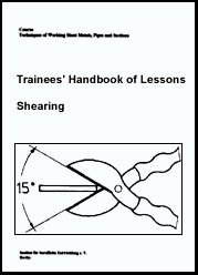
“Scheren”
Author: B. Zierenberg
First edition © IBE
Institut f�r berufliche Entwicklung e.V.
Parkstra�e
23
13187 Berlin
Order No.: 90-35-3113/2
|
| ||||||||||||||||||||||||||||||||||||||||||||||||||
Preliminary Remarks
The present documentation is meant for the training in trades, which require fundamental skills and abilities of machining and processing sheet metals, pipes and sections. The documentation describes the execution of various shearing techniques for sheet metals and sections on shears of different design.
|
| ||||||||||||||||||||||||||||||||||||||||||||||||||
Hints on Labour Safety
- Use gloves when handling larger sheet metal plates - risk of getting injured.
- Only use proper and sharp shears - blade clearance must be adjusted correctly.
- Do not work with jour hands between the blades - risk of getting injured.
- Only let one person operate lever shears and guillotine machines, as for large-size sheets and long sections, a second person may help push them through from the side.
- Correctly adjust the toe dog on lever shears and shearing machines.
- Do not stay within the swiveling range of hand levers during the cutting operation.
- Secure hand lever of the lever shear after the cutting process.
- Only shear steel sections with section knives - never operate on sheets with plane shear blades, otherwise the cutting edges break off.
- Only operate shearing machines after being exactly instructed. Exactly observe the manufacturer’s operating instructions.
- Immediately throw the waste material rendered during the shearing operation into the waste container. Remaining bent rests of cuts may lead to injuries.
|
| ||||||||||||||||||||||||||||||||||||||||||||||||||
1. Purpose of Shearing
Shearing denotes non-chip cutting of sheet-metals and sections. Cuts may be straight-lined or curve-shaped in optional lengths.

Figure 1. Shearing
Compared to sawing and chiselling, shearing has the following advantages:
- No metal is removed from the material.
- Scribed lines can be exactly followed up.
- Joint faces only require little re-work.
- Shearing process is fast.
- Way of cut may be straight-lined and curve-shaped.
Special shearing techniques are:
Cutting-in, cutting off, cutting out, punching
|
| ||||||||||||||||||||||||||||||||||||||||||||||||||
2. Tools and Machines
There are shears of different design for manual or machine operation. Shear selection is mainly determined by sheet thickness and form of cut.
Tinners’ snip
It is used for short straight-lined or short curve-shaped cuts on thin sheet metals.
Maximum sheet thickness:
|
Steel |
- 0.7 mm |
|
Brass |
- 0.8 mm |
|
Copper |
- 1.0 mm |
|
Aluminium |
- 1.0 to 2.5 mm |
Figure 2. Tinners’ snip
Tinners’ through snip
It is employed for longer straight-lined cuts on thin sheets. Since the sheet passes through under one’s hand, there is no danger of getting one’s hand injured.

Figure 3. Tinners’ through snip
Hole cutting shear
It is used to cut curve-shaped thin sheet metal parts. The shear blades curved on one side are not suitable for straight-lined cuts.

Figure 4. Hole cutting shear
Curve shear
It is suited for circular and curve-shaped cuts on thin and medium-thick sheets of up to 4 mm. The sheet may be turned in any direction during the cutting operation.

Figure 5. Curve shear
Guillotine machine
It is employed to cut off thin sheets (about 3 mm) in oversized lengths.
The upper shear blade is stroken against the lower one during the cutting procedure.
There are various designs of guillotine machines being operated either manually or by machine force.

Figure 6. Guillotine machine
1 telescopic hand lever, 2 upper shear blade, 3 lower shear blade, 4 counterweight
Lever shear
It is used for short straight-lined and curve-shaped cuts of medium-thick sheet metals or to cut off sections. The upper shear blade is pivoted and moves down against the lower shear blade via a lever transmission. The hand-lever can be locked to avoid injuries by its falling down. To cut off sections, profiled elements with additional shear blades are arranged over the upper shear blade.

Figure 7. Lever shear
1 frame, 2 section knife holders, 3 upper shear blade, 4 lower shear blade, 5 adjustable hold-down bar, 6 hand lever, 7 hand-lever locking device
Circular shear
It is used for curve-shaped, long cuts on thin and thicker sheet metals.
The roller shear has wheel-shaped shear blades moving to each other in opposite rotating direction. The upper shear blade can be moved up and down to get adjusted to the sheet thickness. As for thicker sheets, several passes are, however, required to completely cut the sheet to pieces.
Roller shears may be operated by hand or by machine force.

Figure 8. Circular shear
Electric tinners’ snip
It is employed to cut thin sheets when curve-shaped cuts are to be made. A small upper shear blade is quickly moved up and down by motor force so that the shear cuts through the sheet by means of continuous feed movement performed by hand.

Figure 9. Electric tinners’ snip
Cutting tools
They are used in various forms for mass production of sheet-metal parts when simple or complicated forms of the same kind are needed. Cutting tools consist at least of one punch and a cutting plate having an accurate-to-size opening. The punch has exactly to fit through the opening, with a cutting clearance of 0.05 to 0.1 mm of sheet thickness between the two tools. The punch is pushed through the sheet in the cutting plate by pressure force. The sheet part falls down under the cutting plate.

Figure 10. Cutting tool
1 punch, 2 cutting plate with opening, 3 punched workpiece
Power-driven shear machine
It is applied to cut very long sheet metals of over 10 mm in thickness as well as stronger sections. This shear machine has a strong, adjustable drive, hydraulically operated hold-down bar and a mechanically operated cutting gap adjusting device. The cutting line can be observed on an indicating appliance.

Figure 11. Power-driven shear machine
1 drive, 2 finger guard, 3 hold-down bar, 4 supporting table
What is the purpose of
shearing?
_____________________________
_____________________________
_____________________________
Which are the advantages of shearing compared to
sawing?
_____________________________
_____________________________
_____________________________
Which different shearing techniques are
there?
_____________________________
_____________________________
_____________________________
Which cuts can be made on the tinners’
snip?
_____________________________
_____________________________
_____________________________
For which cuts is the guillotine machine
used?
_____________________________
_____________________________
_____________________________
For which cuts is the lever shear
employed?
_____________________________
_____________________________
_____________________________
|
| ||||||||||||||||||||||||||||||||||||||||||||||||||
3. General Construction of Shears
The shear blade cutting edges have a great wedge angle (about 80°) so that they are sufficiently stable during the shearing process. Clearance angles of 2° to 3° reduce the friction between shear blades and material. To prevent the blades from rubbing against each other and getting dull, a blade clearance has to be set on the shear in dependence on the material to be cut: blade clearance = 0.5 to 0.1 mm x sheet thickness.

Figure 12. Blade clearance correctly
adjusted
1 upper shear blade, 2 sheet, 3 lower shear blade, 4 blade clearance
Too great a blade clearance results in improper faces of cut and a strong formation of buns. Thin sheets may even be bent off.
The blade clearance also affects the sheet of slightly pitching down that can be compensated by an adjustable hold-down bar on hand-lever shears and shearing machines.

Figure 13. Effect with to great a
blade clearance - sheet is bent off
1 upper shear blade, 2 sheet, 3 lower shear blade

Figure 14. Hold-down bar correctly
adjusted
1 hold-down bar, 2 upper shear blade, 3 sheet, 4 lower shear
On shears having blades that are arranged in parallel, the material is sheared off at the entire cutting edge at one time. In this case, a very strong cutting force is required. To keep the cutting force at a lower state, the upper shear blade is set in an inclined way on most shears.

Figure 15. Shear with parallel shear
blades
1 upper shear blade, 2 lower shear blade
Due to the leverage it is favourable to shove the workpiece as far as possible in the shear jaws because then a great cutting force can be applied.
At the same time, a pushing force is exerted that would shove the workpiece out of the jaws. Only when the workpiece friction on the blades is equal to the pushing force, the cutting process is possible. Then the shear blades form an aperture angle of 15° approximately. To ensure this aperture angle for longer cuts as well, the upper blade has been curve-shaped on great many a shears.

Figure 16. Shear with inclined upper
blade
1 upper blade, 2 rake angle, 3 lower blade
Why do shear blades have a great wedge
angle?
_____________________________
_____________________________
_____________________________
Why has a blade clearance to be
maintained?
_____________________________
_____________________________
_____________________________
What will happen when too great a blade clearance has been
adjusted?
_____________________________
_____________________________
_____________________________
What is the task of the hold-down bar on lever shears and
shearing
machines?
_____________________________
_____________________________
_____________________________
Why is an aperture angle of 15° important for the shearing
process?
_____________________________
_____________________________
_____________________________
|
| ||||||||||||||||||||||||||||||||||||||||||||||||||
4. Mode of Operation of the Shearing Process
In shearing, two wedge-shaped shear blades closely pass by each other. The workpiece that is placed between the two shear blades is cut under continued effect of force. The shearing process is performed in 3 stages:
Notching
When the blades touch down, the material springs back a bit under the effect of force. As soon as its elastic limit has been overcome, the blades notch the workpiece.

Figure 17. Notching
1 upper blade, 2 notched sheet, 3 lower blade
Cutting
In further penetrating, the shear blades overcome the internal resistance of the metal structure and cut the workpiece.

Figure 18. Cutting
1 upper blade, 2 cut-in sheet, 3 lower blade
Tearing
The penetrating shear blades squeeze the material together between the blades, resulting in a material solidification. Since the blades are not able to further penetrate the material, they tear the residual material apart under continued effect of force.
These stages can be seen at joint faces of thick sheets.

Figure 19. Tearing
1 upper blade, 2 torn sheet, 3 lower blade

Figure 20. Sheared joint face
1 upper notch, 2 smooth cut face, 3 rough torn face, 4 lower notch
|
| ||||||||||||||||||||||||||||||||||||||||||||||||||
5. Shearing Techniques
The different shearing techniques are distinguished by the kind of cutting.
Cutting-in
A cut is performed that is only partially penetrating the material. Thus, the material is not cut completely.
Cutting-in is mostly effected in preparing the subsequent bending-off procedure.

Figure 21. Cutting-in for subsequent
bending
Cutting-off
A cut is performed, going through the material completely and thus separating the material. The cut-off and extremely bent material is scrap.
Figure 22. Cutting-off
1 workpiece, 2 waste
Cutting-out
The material is completely cut alongside a line closed in itself.
The material cut out is the workpiece, the rest is scrap.

Figure 23. Cutting-out
1 workpiece, 2 waste
Punching
The material is completely cut alongside a line closed in itself. The material cut out is scrap, the material surrounding is the workpiece.

Figure 24. Cutting-out
1 workpiece, 2 waste
Which stages are passed through in a shearing
process?
_____________________________
_____________________________
_____________________________
What is the difference between the techniques of cutting-out and
punching?
_____________________________
_____________________________
_____________________________
|
| ||||||||||||||||||||||||||||||
Shearing - Course: Technique of working sheet metals, pipes and sections. Trainees' handbook of lessons (Institut f�r Berufliche Entwicklung, 17 p.)
6. Sequence of Selected Shearing Operations
The shearing operations are distinguished by differently handling the various shears.
6.1. Cutting-in Sheets on the Tinners’ Snip
- Scribe sheet as to accurately to size.
- Exactly set shear horizontally with 15° wide jaws onto the scribed line and align.

Figure 25. Tinners’ snip jaws
correctly opened
- Cut in the sheet, but do not close the shear completely, otherwise the sheet is laterally torn at the end of cut.
- Continue shoving the shear by repeatedly opening the jaws.
- Again cut in the sheet up to the preset length.
6.2. Cutting-off the Sheet on the Lever Shear
- Scribe sheet as to accurately to size. In case of improper surface, punch-mark scribed line for control. Scrap side should be the right-hand sheet side, if possible.
- Check blade clearance on shear and re-adjust, if required. Shove sheet far into the shear blades, align scribed line with upper and lower shear blades - scrap side should be right-hand.
- Set hold-down bar on left-hand sheet surface and release hand-lever lockage.
- Pull hand-lever evenly downwards and follow up cutting effect and cutting direction of upper shear blade. As for longer cuts take heed of continuously feeding sheet metal.

Figure 26. Sheet correctly placed on
the lever shear
1 workpiece side, 2 waste side
|
Do not completely lower the upper shear blade, as the shear blade end causes transverse cracks in the sheet! |
- Completely cut the sheet through at the end - again lock the hand lever.
- Release toe dog and pull sheet out of the shear.
- Immediately throw the extremely bent waste material always rendering on the shear’s right-hand side (in line of vision to the shear) into the waste container.
|
Do not let cut-off and bent sheet pieces lie on ground - risk of getting injured |
What is to be expected in the sheet metal when the shear blades
are completely
closed?
_____________________________
_____________________________
_____________________________
Why should the scrap side of a sheet be always situated on the
right-hand sheet
side?
_____________________________
_____________________________
_____________________________
6.3. Cutting-off Angular Sections on the Lever Shear
- Scribe length of angle section accurately to size. Scribe the line inside.
- Shove angular section through the shear’s angular-profiled blade (in line of vision to the shear).
- Align scribed line with upper shear blade.
- Release hand lever locking device.
- Pull down hand lever with a jerk.
- Pull angular section out of the shear. Throw waste par into the waste container.

Figure 27. Correct section knife for
the shearing of angles
Why must steel sections be cut with section
knives?
_____________________________
_____________________________
_____________________________
What will happen when steel sections are cut on plane shear
blades?
_____________________________
_____________________________
_____________________________
Why must the hand lever of the lever shear be locked after the
cutting
operation?
_____________________________
_____________________________
_____________________________
Why must waste material rendered during the shearing operation
be immediately thrown into the waste
container?
_____________________________
_____________________________
_____________________________